

A few weeks ago, I posted article named "DCC ready" board for classical locomotive (DC loco) where it presented how can be use the "DCC ready" board
 --->
---> 
For add the NEM652 decoder on DCC ready board you must remove small 8-pin board and connect the decoder:
- initial


- remove 8-pin board

- add NEM652 decoder, with correct position


I used for tests:
- 0-30V/0-10A power supply (set to 12V voltage & 2A maximum current)
- Arduino Mega board (clone)
- Arduino Motor shield (clone)
- LCD1602 display + i2c interface (added later)
First I cut trace for VIN as in article from https://dcc-ex.com/get-started/assembly.html
- initial (using a DMM on diode domain, test if resistance is near 0Ω)


- after (using a DMM on diode domain, test if resistance is big, OL - open load on display)


I make a video named test a DCC decoder (NEM652) with Arduino Web Throttle where I presented how I used the Web Throttle and how react board with NEM652 decoder.
Later, I added LCD1602display with i2c interface and I used again installer. Decimal address is 63 for 3F as hexa number for i2c interface adsress
On display of command station is shown logo

or state of decoder


Adapter board + NEM652 decoder + bicolor led as "locomotive" and Arduino Mega + Motor Shield + display as command station:
- forward
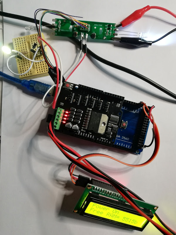
- backward

20.04.2022
I want to find if my decoder has active Function 1 (pin 3) and Function 2 (free purple wire) so I added a green led at pin 3 in series with 3k3 resistor to pin 7 (common V+), also I added a yellow led at free purple wire in series with 3k3 resistor to pin 7 (common V+). Usual value for serie resistor is 1kΩ, but 3k3 was in my way.


I tested also Function 1 (Bell) and Function 2 (Horn)


22.04.2022
I tested the system with Android Throttle (Engine Driver application) and I make a video named test NEM decoder with DCC++EX Arduino Station and Android Throttle. For this situation, information on LCD display are very useful (IP and Port).


