Total Pageviews

Showing posts with label RTC. Show all posts

Saturday, November 26, 2016

FDS-125 display with Arduino (2)

original article


   In previous article I present you how can conect an FDS-125 display to Arduino and how mase a simple, but "static" clock style
   For made an "dynamic" clock, I use some schematic
  I write in exitting sketch to display name of day in week in 2 language (romanian who is my navitve language and in english). It easy to change in your navive language by writting name of days in one line:
  Is very important to have in same subdyrectory of sketch font75.h file like in this picture:
  So, by uploading FDS125_clock1b.ino sketch, you cand see on display new info, beside date:
   In Arduino clock on FDS-125 display (2) movie you can see on FDS-125 display all info:
   After that, I put an AM2302 (DHT22) sensor for humidity and temperature, like in next picture:
   Newest skertch is FDS125_clock_RTC1c.ino and on display you can see new situations:
   Because, DHT sensor is too slow when is reading, I made some changes to see temperature and humidity in same times, also I chege font75.h file to display degree symbol instead ': 
  New sketch is FDS125_clock_RTC1c1.ino and this new style can be see it on Arduino clock on FDS-125 display (4)

FDS-125 display with Arduino

original article

   This display was received from Janos Baricz, vintage things passionate. On webworld, we find just some info and tests with FDS-132 display who is bigger than FDS-125.
   So, you can see info about "big brother" at:
   FDS-125 display has 2 big rows, each with 7 rows and 60 columns (12 matrix 5x7 leds) controlled by Lattice MACH21 microcontroller.
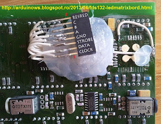
   For control by Arduino must extract Lattice MAC21 microntroller and put few wires like in this pictures from arduinows.blogspot.com:
   Janos made hardware part for this display:
and in this case, situation is:
- green wire is A from FDS-125 display, must connect to D5 pin at Arduino board
- pink wire is B from FDS-125 display, must connect to D6 pin at Arduino board
- white wire is C from FDS-125 display, must connect to D7 pin at Arduino board
- yellow wire is STROBE from FDS-125 display, must connect to D10 pin at Arduino board 
- mauve wire is DATA from FDS-125 display, must connect to D11 pin at Arduino board 
- grey wire is CLOCK from FDS-125 display, must connect to D13 pin at Arduino board 
- blue wire is RESRED from FDS-125 display, must connect to D9 pin at Arduino board 
- black wire is GND from FDS-125 display, must connect to GND pin at Arduino board 
Also, on the back site is power for display (in picture is a red wire connected from power conector at power of display part).
  I redesigned connexion between FDS-125 display and Arduino board:
   After that, I tested some sketches and I "lit" the display
   I put an RTC clock made with DS3231 (works fine with DS1307, also) and adapt an sketch from arduinoforum.nl made for FDS-132. Result is FDS125_clock.ino sketch and test schematic is:
   Whem upload the sketch on display is on top row is data and on bottom row is hour:
   Also, I made Arduino clock on FDS-125 display movie to see how clock is..

Tuesday, November 22, 2016

Vintage HDLO-2416 display

original article


    I received from an enthusiast of wintage displays, Janos Baricz, a module with 5 HDLO-2416 displays.
   HDLO-2416 display was made by Avago Technologies and has this datasheet.
    After I talk with Janos, him made a module with 5 displays after test one display with sketch from http://gorgusgfx.se/?page_id=62 and IntMatrixDisp library.
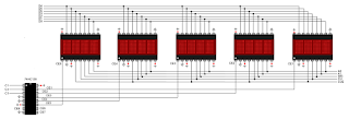
    Module has this schematic:
and has different colour for eatch wire...
    First, I test sketch from http://gorgusgfx.se/?page_id=62 with next connexions:
and on displays I can see 5 texts identical:
   After that, I put CE1 at A0, CE2 at A1, CE3 la A2, CE4 at A3 and CE5 at A4.
   I write a sketch for test this schematic:
  Because this schematic need too much wires, I put an 74HC138 chipo like in docs from IntMatrixDisp library to have free more pins from Arduino:
or more detailled:
   Real montage is now
   Next step was to put an humidity and temperature sensor (DHT22/AM2302) at D12 pin.
 I use sketch from https://github.com/tehniq3/HDLO-2416/blob/master/HDLO2416_DHT1.ino and on display I see few seconds humidity and than temperature:
   Further, I put an DS3231 RTC module at i2c pins and use HDLO2416_DHT_RTC1.ino sketch.
   In movie named RTC clock with DHT weather data on HDLO-2416 display you can see how animate is display (few seconds you can see temperatura, few seconds you can see relative humidity from air, more seconds you can see data and hour):


Adjusting dual clock using DS3231 on 1.8" ST7735 display

  I change the sketch for create a dual clock (GMT/UTC and local time), but I use same schemtic as in article Adjuting clock with thermometer using DS3231 on 1.8" ST7735 display
  Last version of uploaded sketch is TFT_DualDigitalClock_RTC2.ino. Also, I made a movie named adjuting dual clock using DS3231 on 1.8" ST7735 display for see how the clock can be adjusted (hour, minute, name of day, year, month, day, difference between local time and UTC/GMT):


Wednesday, November 9, 2016

Another adjusting clock with alarm & thermometer using DS3231 on 1.8" ST7735 display

   I use some schematic as in previous article  but is different sketch.
   I adapted original sketch from educ8s.tv to use manual adjustment for date and hour, alarm. Also, I remove RTC library and use subroutines for set and read data and hour, for read inside temperature of DS3231, alse I stored in EEPROM memory hour, minute and state of alarm.
  Last sketch is educ8stv_rtctft160_alarm_eeprom.ino with all features. Also state of alarm is shown by colour of alarm value and sign:
- alarm is waiting (activated)
- alarm is off (deactivated)
- alarm is on 
   You can see how work tthis version of the clock with alarm, hour & data adjustment in movie named another adjusting clock with alarm & thermometer using DS3231 on 1.8" ST7735 display