Total Pageviews

Showing posts with label dht22. Show all posts

Friday, August 24, 2018

Show Temperature and Humidity as WiFi SSID with ESP8266 and DHT22 Sensor

   I use informations from article Show Temperature and Humidity as WiFi SSID with ESP8266 and HTU21D Sensor, just change sensor. Instead HTU21D, I use DHT22 (AM2302), my schematic is
   I program NodeMCU development board (work any development board with ESP8266: Lolin, Adafruit, WeMos, etc) with Arduino IDe software, using dht_custom_ssid_exp8266_1.ino sketch.
   For frogram ESP8266 as Arduino must follow steps from เพิ่มบอร์ด ESP8266 ใน Arduino IDE (or from my article named Placa NodeMcu v.0.9 programata in Arduino IDE).
  Also, you need 3 library:
- DHT
Pstring
Streaming
   Now, we can find Wi-Fi network with custon name (ESP8266 is in AP mode):
- on Android phone
- on PC with Windows 7
   Name of SSID will change at every 10 seconds, but best view is in Android phone (quick change).
   I made Show Temperature and Humidity as WiFi SSID with ESP8266 and DHT22 Sensor video to see how this system work:


Wednesday, November 30, 2016

Another adjusting clock with alarm, hygrometer & thermometer on 1.8" ST7735 display

   I use feature from article Another adjusting clock with alarm & thermometer using DS3231 on 1.8" ST7735 display and change reading internal temperature of DS3231 with DHT22 senzor (AM2302), but you can use a cheaper and not very precise DHT11 senzor.
   Schematic is now:
   My test montage is
   By using educ8stv_rtctft160_alarm_dht.ino or much better educ8stv_rtctft160_alarm_eeprom_dht.ino sketch, on display you can see: name of day, date, hour clock, hour alarm, temperature and humidity
   In another adjusting clock with alarm, thermometer & hygrometer using DS3231 on 1.8" ST7735 display you can see info on display and hoe change/adjust hour, data, hour alarm, activate and deactivate alarm, etc:
   Alse, I made another movie, named another adjusting clock with alarm, thermometer & hygrometer using DS3231 on 1.8" ST7735 display (2), where I try to explain more detailed the feature of this clock...

Friday, August 12, 2016

Itron FG209M2 vfd display controlled by Arduino via 2 MAX6921

see about this article on HACKADAY ;)


   I give for tests an old vfd display made by Itron with 20 characters each made with 14 segments, point & comma.
   Janos, who is owner of this vfd display, made a interface with 2 MAX6921 integrated, using this schematic:
and PCB board is
   I redesigned schematic of vfd interface using Eagle PCB software
   After I study the datasheet of MAX6921, for send data to vfd display, classical style is:
 but in my case is little different because I have cascaded 2 MAX6921; for put on vfd display letter R on left corner must send this data:
with this notation of segments of character:
   For initial test, I made a simple schematic, using fist time an Arduino Mega board, than Arduino Uno:
   When upload VFD_FG209M2_2MAX6921_test1.ini sketch I see X letter moving from right to left of vfd display, like in video named 

   I made small steps (create characters, like in application note for MAX6954 (see https://www.maximintegrated.com/en/app-notes/index.mvp/id/3211)
 until I simulate a clock with calendar and temperature and humidity using VFD_FG209M2_2MAX6921_test3j3c.ini sketch, see movie named afisaj VFD FG209M2 cu MAX6921 si Arduino (9)

   Finally, I put in schematic an RTC module with DS3231 (works fine with DS1307, too) and DHT22 module (AM2302 sensor + 4k7 resistor between +5V and DATA pin) for humidity and temperature:
   Using RTC_DHT_VFD_FG209M2_2MAX6921_ver4.ino I have on vfd display next texts:
   Because texts are in my native language (roumanian) I made few changes for have alternative indications:
NOTE: More details about steps in experiments can be writte in original article !

   I reduce previous sketch and remain just english text for day & day, current sketch is RTC_DHT_VFD_FG209M2_2MAX6921_ver4b.ino and you can see how is now in movie named clock on VFD FG209M2 display with MAX6921 and Arduino (3)

1-March-2021
   I received from Janos new info for display
also I received the schematic for power the VFD:

Monday, July 6, 2015

KTM-S1201: 12 Digit 7-segment LCD display

original article !!

   Like SDA5708: 8 character 7x5 dot matrix LED display, this display is received as gift for test.
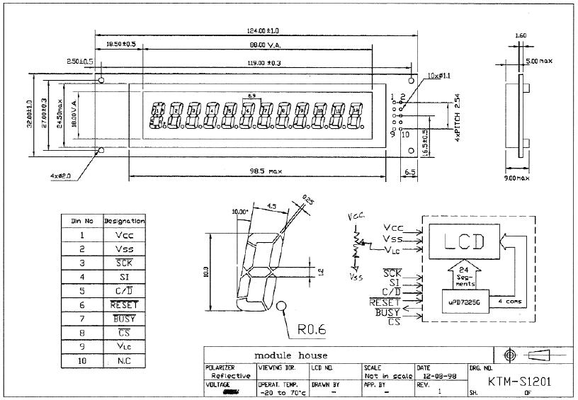
   KTM-S1201 display is drived by NEC D7225 (UPD7225G) chip and I found a very usefull article named Arduino and KTM-S1201 LCD modules
   I use also info from www.pongrance.com
   For control this display with Arduino sketch must download KTMS1201.h file and put in same directory with sketch:
and in Arduino IDE software you see:
   First step was to made a pcb for schematic with a 10..20k variable resistor for contrast:
   Schematic is made after nest info:
   Test schematic is:
   After upload the example sketches and few changes in sketches, on display I can see:
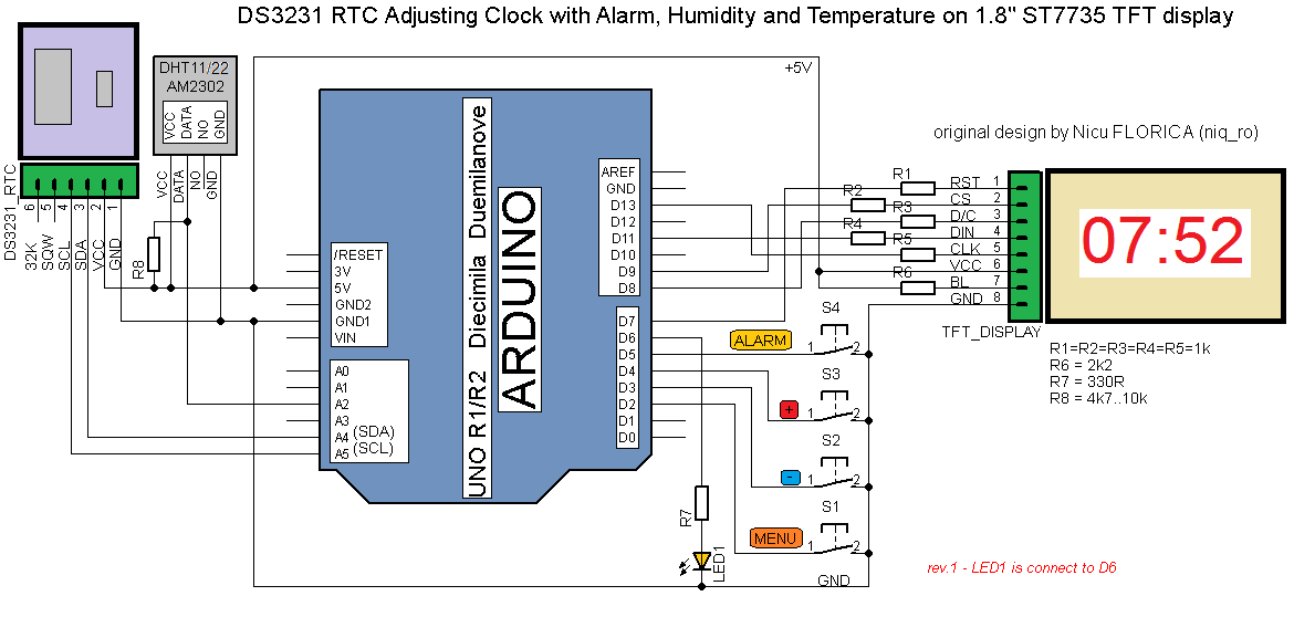
   After that, I made a new schematic with DHT22 (AM2302) sensor:
   I write a sketch named KTMS1201_DHT22.ino and on display I can see:
   I finished the schematic with RTC clock module (made with DS3231, but work fine with DS1307) and KY-040 rotary encoder:
After upload KTMS1201_DHT22_RTC_ver1m0.ino sketch, I cand see:
- hour:
- humidity and temperature:
- data, after a short push:
- change mode, first year, after a long push (3-4 seconds):
- change month:
- change day:
- change hours:
- change minutes:
   I made few movie:
    Final sketch is KTMS1201_DHT22_RTC_ver1m1.ino and I use a changed KTMS1201.h file for C and Y letters:
   Finally, I change the sketch (see KTMS1201_DHT22_RTC_ver1m1b.ino) for another style for humidity: