I try more version, and now I present you a AC light dimmer with 2 push buttons for 16 steps and a alphanumerical LCD1602 display. I use 100W incandescent bulb at 230V/50Hz.
My schematic is:


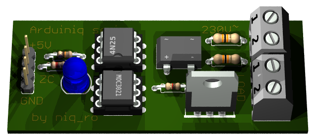
My handmade module is:


In my case, I have 16 steps of intensity of bulb:
- bulb is off (0%):

- 1st step (6%):

- 2nd step (13%):

- 3rd step (19%):

- step no.4 (25%):

- stept no.5 (31%):

- step no. 6 (38%):

- step no.7 (44%):

- step no.8 (50%):

- step no.9 (57%):

- step no.10 (63%):

- step no.11 (69%):

- step no.12 (75%):

- step no.13 (82%):

- step no.14 (88%):

- step no.15 (94%):

- last step (100%), bulb is at maximum:

My sketch is:
/*
AC Light Control
 Updated by Robert Twomey <rtwomey@u.washington.edu>
 Thanks to http://www.andrewkilpatrick.org/blog/?page_id=445
 and http://www.hoelscher-hi.de/hendrik/english/dimmer.htm
 adapted sketch by niq_ro from
 http://www.tehnic.go.ro
 http://www.niqro.3x.ro
 http://nicuflorica.blogspot.com &  http://arduinotehniq.blogspot.com
*/

#include <LiquidCrystal.h>
// use LiquidCrystal.h library for alphanumerical display 1602
LiquidCrystal lcd(13,12,11,10,9,8);
/*                                     -------------------
                                       |  LCD  | Arduino |
                                       -------------------
 LCD RS pin to digital pin 13          |  RS   |   D13   |
 LCD Enable pin to digital pin 12      |  E    |   D12   |
 LCD D4 pin to digital pin 11          |  D4   |   D11   |
 LCD D5 pin to digital pin 10          |  D5   |   D10   |
 LCD D6 pin to digital pin 9           |  D6   |    D9   |
 LCD D7 pin to digital pin 8           |  D7   |    D8   |
 LCD R/W pin to ground                 |  R/W  |   GND   |
                                       -------------------
*/
#include <TimerOne.h>           // Avaiable from http://www.arduino.cc/playground/Code/Timer1

volatile int i=0;               // Variable to use as a counter
volatile boolean zero_cross=0;  // Boolean to store a "switch" to tell us if we have crossed zero
int AC_pin = 3;                 // Output to Opto Triac
int buton1 = 4;                 // first button at pin 4
int buton2 = 5;                 // second button at pin 5
int dim2 = 0;                   // led control
int dim = 128;                  // Dimming level (0-128)  0 = on, 128 = 0ff
int pas = 8;                    // step for count;
// version: 4m7 (15.04.2013 - Craiova, Romania) - 16 steps, 4 button & LED blue to red (off to MAX)
// version: 7m3 (22.01.2014 - Craiova, Romania) - 16 steps, 2 button & LCD1602

int freqStep = 75;    // This is the delay-per-brightness step in microseconds for 50Hz (change the value in 65 for 60Hz)


void setup() {  // Begin setup
  Serial.begin(9600);
  pinMode(buton1, INPUT);  // set buton1 pin as input
  pinMode(buton2, INPUT);  // set buton1 pin as input
  pinMode(AC_pin, OUTPUT);                          // Set the Triac pin as output
  attachInterrupt(0, zero_cross_detect, RISING);    // Attach an Interupt to Pin 2 (interupt 0) for Zero Cross Detection
  Timer1.initialize(freqStep);                      // Initialize TimerOne library for the freq we need
  Timer1.attachInterrupt(dim_check, freqStep);
  // Use the TimerOne Library to attach an interrupt

 lcd.begin(16, 2); // set up the LCD's number of columns and rows:
 lcd.clear(); // clear the screen
 lcd.setCursor(2, 0); // put cursor at colon 0 and row 0
 lcd.print("16 steps AC"); // print a text
 lcd.setCursor(0, 1); // put cursor at colon 0 and row 1
 lcd.print("dimmer for bulb"); // print a text
 delay (3000);
 lcd.clear(); // clear the screen
 lcd.setCursor(1, 0); // put cursor at colon 0 and row 0
 lcd.print("this sketch is"); // print a text
 lcd.setCursor(1, 1); // put cursor at colon 0 and row 1
 lcd.print("made by niq_ro"); // print a text
 delay (3000);
 lcd.clear(); // clear the screen
}

void zero_cross_detect() {
  zero_cross = true;               // set the boolean to true to tell our dimming function that a zero cross has occured
  i=0;
  digitalWrite(AC_pin, LOW);
}

// Turn on the TRIAC at the appropriate time
void dim_check() {
  if(zero_cross == true) {
    if(i>=dim) {
      digitalWrite(AC_pin, HIGH);  // turn on light
      i=0;  // reset time step counter
      zero_cross=false;    // reset zero cross detection
    }
    else {
      i++;  // increment time step counter
    }
  }
}

void loop() {
  digitalWrite(buton1, HIGH);
  digitalWrite(buton2, HIGH);

 if (digitalRead(buton1) == LOW)
   {
  if (dim<127)
  {
    dim = dim + pas;
    if (dim>127)
    {
      dim=128;
    }
  }
   }
  if (digitalRead(buton2) == LOW)
   {
  if (dim>5)
  {
     dim = dim - pas;
  if (dim<0)
    {
      dim=0;
    }
   }
   }
    while (digitalRead(buton1) == LOW) {  }
    delay(10); // waiting little bit...
    while (digitalRead(buton2) == LOW) {  }
    delay(10); // waiting little bit...


  dim2 = 255-2*dim;
  if (dim2<0)
  {
    dim2 = 0;
  }

  Serial.print("dim=");
  Serial.print(dim);

  Serial.print("     dim2=");
  Serial.print(dim2);
  Serial.print("     dim1=");
  Serial.print(2*dim);
  Serial.print('\n');
  delay (100);
 lcd.setCursor(2, 0); // put cursor at colon 0 and row 0
 lcd.print("power is "); // print a text
 lcd.print(100-100*(255-dim2)/255);
 lcd.print("%    "); // print a text
 lcd.setCursor(1, 1); // put cursor at colon 0 and row 1
 lcd.print("dim. level="); // print a text
 lcd.print(dim);
 lcd.print("  "); // print a text
}
NOTE: For 60Hz must change
int freqStep = 75;
in int freqStep = 65;
!
I made 2 movies with this AC light dimmer:
- ac light dimmer with Arduino (XVII)You can made PCB using lay file from http://arduinolab.pw and you can download Sprint Layout Viewer for open this file...