Total Pageviews

Showing posts with label locomotive. Show all posts

Thursday, June 23, 2022

Railway Crossing Multi Track Two Way

    This article is based on the article with same name and Railway Crossing Part 4: Putting it all Together article.

   My tests included few models until at last version with sounds (warnings) and other count method for trains, but main structures are same:

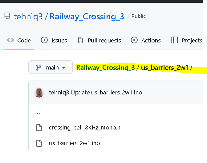
Railway_Crossing_1 (just added tip and free lights), sketch: us_barriers_rudysarduinoprojects_1b.ino


Railway_Crossing_2 (added sounds using Mike Osborn MKO tips),sketch: bell_and_button_servo_4
Railway_Crossing_3 (added sounds and test different count methods: original with few updates or big changes)
with 3 sketches 
   For last sketch, I uploaded this videos:
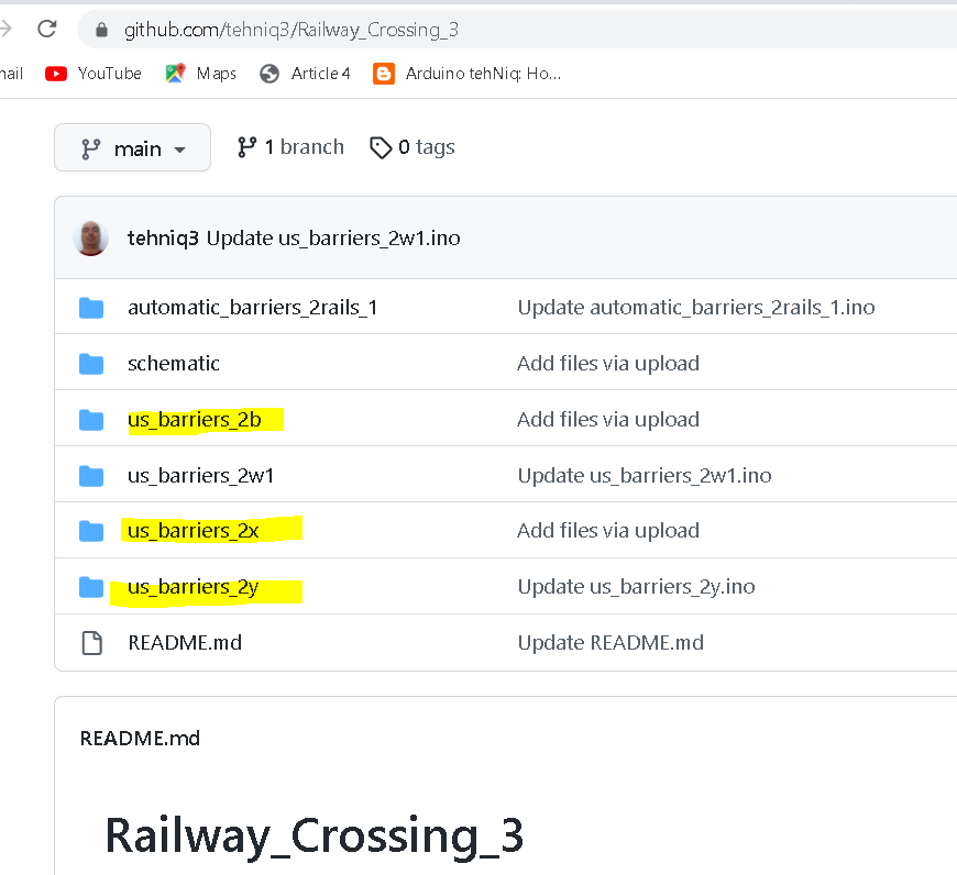
Railway Crossing with lights and sounds for Multi Track Two Way
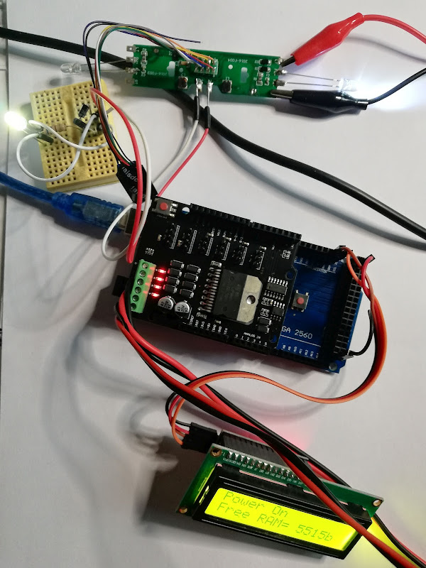
   If no train between IR sensors, barriers (gates) are open:
but at least a train is between sensors, barriers (gates) are closed:


29.08.2022
   I changed the sketch for remove sound after gate is open (us_barriers_2b_2)
as Jedidiah Sawyer wanted. 
   Last change of the sketch is to have also fading light as in 2nd Avenue Railroad Crossing, Clanton, AL

so, last sketch is us_barriers_2b_3
and a short video made by Jedidiah Sawyer:

31.08.2022
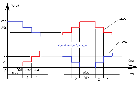
   The variable for change the fade effects are:
and the fade for LED3 is
so, LED3 is off (brightness = 0), than after 200ms (variable time_to_stop) brightness increased at 1 (variable fadeAmount), than after 2 ms (variable fade_delay) brightness is 2, after more 2ms brightness is 4, etc, until brightness is 255 (maximum = 100%) .. is a pause (time_to_stop = 200ms) and after that brightness decrease with 1 at every 2ms until 0... 
Leds for blink effect (LED1 and LED2) are same period as fadding leds (LED3and LED4):
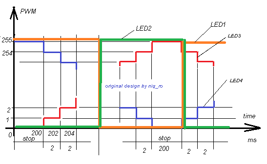
..so, you can change the values as you want,...

Tuesday, April 19, 2022

How to test NEM652 decoder with "DCC ready" board

 original article

   A few weeks ago, I  posted article named "DCC ready" board for classical locomotive (DC loco) where it presented how can be use the "DCC ready" board 

--->   

   I'm beginner in DCC so I try to show you how can test a NEM652 decoder on a DCC ready board. Later, I'll show you how you can install the decoder in your locomotive.
   
  For add the NEM652 decoder on DCC ready board you must remove small 8-pin board and connect the decoder:
- initial

- remove 8-pin board
- add NEM652 decoder, with correct position 


   I found some info about the NEM652 decoder:
   In order to test the decoder I used info and files from https://dcc-ex.com/index.html
   I used for tests:
- 0-30V/0-10A power supply (set to 12V voltage & 2A maximum current)
- Arduino Mega board (clone)
- Arduino Motor shield (clone)
- LCD1602 display + i2c interface (added later)
   First I cut trace for VIN as in article from https://dcc-ex.com/get-started/assembly.html
- initial (using a DMM on diode domain, test if resistance is near 0Ω)
- after (using a DMM on diode domain, test if resistance is big, OL - open load on display)
  I used easy way using installer for sketch in Arduino as in article from https://dcc-ex.com/get-started/installer.html
  For controller (Throttle) I used a web throttle as in article from https://dcc-ex.com/get-started/controllers.html
    I used an Automatic white/red light for analog locomotive (DC) instead DC motor:
    I make a video named test a DCC decoder (NEM652) with Arduino Web Throttle where I presented how I used the Web Throttle and how react board with NEM652 decoder.
   Later, I added LCD1602display with i2c interface and I used again installer. Decimal address is 63 for 3F as hexa number for i2c interface adsress

On display of command station is shown logo
or state of decoder
Adapter board + NEM652 decoder + bicolor led as "locomotive" and Arduino Mega + Motor Shield + display as command station:
- forward
- backward

20.04.2022
    I want to find if my decoder has active Function 1 (pin 3) and Function 2 (free purple wire) so I added a green led at pin 3 in series with 3k3 resistor to pin 7 (common V+), also I added a yellow led at free purple wire in series with 3k3 resistor to pin 7 (common V+). Usual value for serie resistor is 1kΩ, but 3k3 was in my way.
   I make another video, named test a DCC decoder (NEM652) with Arduino Web Throttle - 2, where you see how I control "digital locomotive" through Web Throttle 
    Later, I added a wi-fi board with ESP8266-01 at Station:
and I uploaded sketch in Arduino Mega using the installer:
after I find channel for my wi-fi (bbk2 - channel 4):
On display we see the IP adress and port for station:
   I install Engine Driver application on my Android phone (see more info about aplication in article Choosing a Controller (Throttle)
   I tested also Function 1 (Bell) and Function 2 (Horn)

22.04.2022
   I tested the system with Android Throttle (Engine Driver application) and I make a video named test NEM decoder with DCC++EX Arduino Station and Android Throttle. For this situation, information on LCD display are very useful (IP and Port).