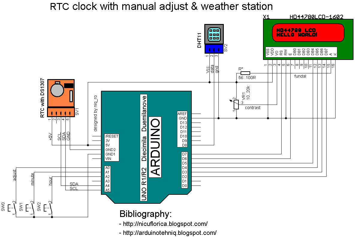
I use a Arduino Uno board as "brain", a DHT11 sensor for humidity and temperature & RTC module with DS1307 for time and values are put on a alphanumeric LCD1602 display.
My last schematic is:
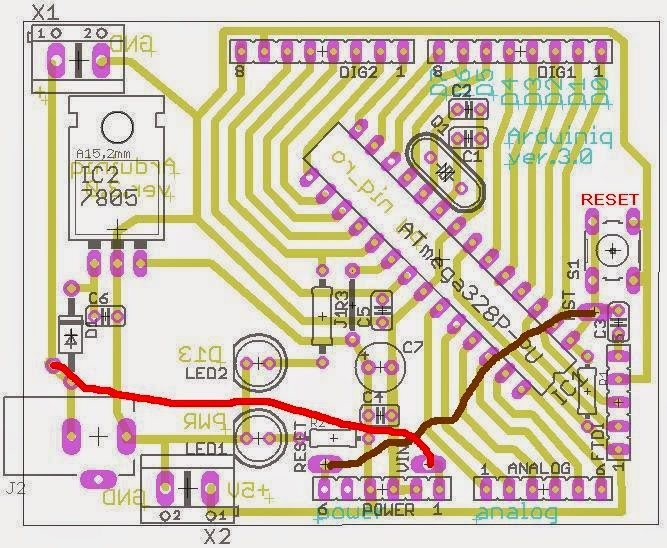
Practically, my montage is:
// Date and time functions using a DS1307 RTC
// original sketck from http://learn.adafruit.com/ds1307-real-time-clock-breakout-board-kit/
// add part with SQW=1Hz from http://tronixstuff.wordpress.com/ & http://www.bristolwatch.com/arduino/arduino_ds1307.htm
// adapted sketch by niq_ro from http://nicuflorica.blogspot.ro/
// original article from http://nicuflorica.blogspot.ro/2013/06/ceas-de-timp-real-rtc-cu-ds1307-si.html

#include <Wire.h>
#include "RTClib.h"

// include the library code:
#include <LiquidCrystal.h>
// initialize the library with the numbers of the interface pins
LiquidCrystal lcd(7, 6, 5, 4, 3, 2);

/*                                    -------------------
                                      |  LCD  | Arduino |
                                      -------------------
 LCD RS pin to digital pin 7          |  RS   |   D7    |
 LCD Enable pin to digital pin 6      |  E    |   D6    |
 LCD D4 pin to digital pin 5          |  D4   |   D6    |
 LCD D5 pin to digital pin 4          |  D5   |   D4    |
 LCD D6 pin to digital pin 3          |  D6   |   D3    |
 LCD D7 pin to digital pin 2          |  D7   |   D2    |
 LCD R/W pin to ground                |  R/W  |   GND   |
                                      -------------------
*/

RTC_DS1307 RTC;

#include <DHT.h>
#define DHTPIN 8     // what pin we're connected DHT11
#define DHTTYPE DHT11   // DHT 11
DHT dht(DHTPIN, DHTTYPE);

byte SW0 = A0;
byte SW1 = A1;
byte SW2 = A2;

// use for hexa in zecimal conversion
int zh, uh, ore;
int zm, um, miniti;


void setup () {
  // DHT init
  dht.begin();
  // set up the LCD's number of columns and rows:
  lcd.begin(16, 2);
  // Print a logo message to the LCD.
  lcd.print("www.tehnic.go.ro");
  lcd.setCursor(0, 1);
  lcd.print("creat de niq_ro");
  delay (2500);
  lcd.clear();

   // Serial.begin(9600);
    Wire.begin();

// part code from http://tronixstuff.wordpress.com/
Wire.beginTransmission(0x68);
Wire.write(0x07); // move pointer to SQW address
Wire.write(0x10); // sends 0x10 (hex) 00010000 (binary) to control register - turns on square wave
Wire.endTransmission();
// end part code from http://tronixstuff.wordpress.com/

    RTC.begin();
  if (! RTC.isrunning()) {
    //Serial.println("RTC is NOT running!");
    // following line sets the RTC to the date & time this sketch was compiled
    RTC.adjust(DateTime(__DATE__, __TIME__));
  }

 pinMode(SW0, INPUT);  // for this use a slide switch
  pinMode(SW1, INPUT);  // N.O. push button switch
  pinMode(SW2, INPUT);  // N.O. push button switch

  digitalWrite(SW0, HIGH); // pull-ups on
  digitalWrite(SW1, HIGH);
  digitalWrite(SW2, HIGH);

}

void loop () {
   DateTime now = RTC.now();
  int h = dht.readHumidity();
  int t = dht.readTemperature();

   lcd.setCursor(4, 0);
   if ( now.hour() < 10)
   {
     lcd.print(" ");
     lcd.print(now.hour(), DEC);
   }
   else
   {
   lcd.print(now.hour(), DEC);
   }
   lcd.print(":");
   if ( now.minute() < 10)
   {
     lcd.print("0");
     lcd.print(now.minute(), DEC);
   }
   else
   {
   lcd.print(now.minute(), DEC);
   }
   lcd.print(":");
   if ( now.second() < 10)
   {
     lcd.print("0");
     lcd.print(now.second(), DEC);
   }
   else
   {
   lcd.print(now.second(), DEC);
   }
     lcd.print(" ");

  lcd.setCursor(1, 1);
  // lcd.print("t=");
    if ( t < 10)
   {
     lcd.print(" ");
     lcd.print(t);
   }
   else
   {
   lcd.print(t);
   }
   //lcd.print(",0");
   lcd.write(0b11011111);
   lcd.print("C");

/*   lcd.setCursor(0, 1);
    if ( now.day() < 10)
   {
     lcd.print("0");
     lcd.print(now.day(), DEC);
   }
   else
   {
   lcd.print(now.day(), DEC);
   }
   lcd.print("/");
   if ( now.month() < 10)
   {
     lcd.print("0");
     lcd.print(now.month(), DEC);
   }
   else
   {
   lcd.print(now.month(), DEC);
   }
   lcd.print("/");
   lcd.print(now.year(), DEC);
   lcd.print(" ");
*/
   lcd.setCursor(10, 1);
  // lcd.print("H=");
   lcd.print(h);
   lcd.print("%RH");

   if (!(digitalRead(SW0))) set_time(); // hold the switch to set time


   delay(500);
}

void set_time()   {
  byte minutes1 = 0;
  byte hours1 = 0;
  byte minutes = 0;
  byte hours = 0;

  while (!digitalRead(SW0))  // set time switch must be released to exit
  {
    minutes1=minutes;
    hours1=hours;


    while (!digitalRead(SW1)) // set minutes
    {
     minutes++;
   // converting hexa in zecimal:
    zh = hours / 16;
    uh = hours - 16 * zh ;
    ore = 10 * zh + uh;
    zm = minutes / 16;
    um = minutes - 16 * zm ;
    miniti = 10 * zm + um;

  /*
     for(int i = 20 ; i >0  ; i--) {
     displayNumber01(ore*100+miniti);
     }
   */
   lcd.setCursor(4, 0);
   if ( ore < 10)
   {
     lcd.print(" ");
     lcd.print(ore);
   }
   else
   {
   lcd.print(ore);
   }
   lcd.print(":");
   if ( miniti < 10)
   {
     lcd.print("0");
     lcd.print(miniti);
   }
   else
   {
   lcd.print(miniti);
   }
   lcd.print(":");
   lcd.print("00");

      if ((minutes & 0x0f) > 9) minutes = minutes + 6;
      if (minutes > 0x59) minutes = 0;
      Serial.print("Minutes = ");
      if (minutes >= 9) Serial.print("0");
      Serial.println(minutes, HEX);
    delay(150);
    }

    while (!digitalRead(SW2)) // set hours
    {
     hours++;

   // converting hexa in zecimal:
    zh = hours / 16;
    uh = hours - 16 * zh ;
    ore = 10 * zh + uh;
    zm = minutes / 16;
    um = minutes - 16 * zm ;
    miniti = 10 * zm + um;

   /*
     for(int i = 20 ; i >0  ; i--) {
     displayNumber01(ore*100+miniti);
     }
   */
   lcd.setCursor(4, 0);
   if ( ore < 10)
   {
     lcd.print(" ");
     lcd.print(ore);
   }
   else
   {
   lcd.print(ore);
   }
   lcd.print(":");
   if ( miniti < 10)
   {
     lcd.print("0");
     lcd.print(miniti);
   }
   else
   {
   lcd.print(miniti);
   }
   lcd.print(":");
   lcd.print("00");

      if ((hours & 0x0f) > 9) hours =  hours + 6;
      if (hours > 0x23) hours = 0;
      Serial.print("Hours = ");
      if (hours <= 9) Serial.print("0");
      Serial.println(hours, HEX);
    delay(150);
    }

    Wire.beginTransmission(0x68); // activate DS1307
    Wire.write(0); // where to begin
    Wire.write(0x00);          //seconds
    Wire.write(minutes);          //minutes
    Wire.write(0x80 | hours);    //hours (24hr time)
    Wire.write(0x06);  // Day 01-07
    Wire.write(0x01);  // Date 0-31
    Wire.write(0x05);  // month 0-12
    Wire.write(0x09);  // Year 00-99
    Wire.write(0x10); // Control 0x10 produces a 1 HZ square wave on pin 7.
    Wire.endTransmission();

    // converting hexa in zecimal:
    zh = hours / 16;
    uh = hours - 16 * zh ;
    ore = 10 * zh + uh;
    zm = minutes / 16;
    um = minutes - 16 * zm ;
    miniti = 10 * zm + um;

   /*  for(int i = 20 ; i >0  ; i--) {
     displayNumber01(ore*100+miniti);
     }
 //  delay(150);
    */

   lcd.setCursor(4, 0);
   if ( ore < 10)
   {
     lcd.print(" ");
     lcd.print(ore);
   }
   else
   {
   lcd.print(ore);
   }
   lcd.print(":");
   if ( miniti < 10)
   {
     lcd.print("0");
     lcd.print(miniti);
   }
   else
   {
   lcd.print(miniti);
   }
   lcd.print(":");
   lcd.print("00");
}


