A reader of my blogs announce my this issue about wrong conversion of the date/year when extract data from Unix Time (Epoch Time). Also, the solution for this issue is simple, like here: https://github.com/arduino-libraries/NTPClient/issues/149.
I open the Serial Monitor and epochTime is ok, but conversion to date not
- 1st step: TOOLS -> BOARD -> BOARD MANAGER
- 2nd step: ssearch ESP8266
- 3th step: search 2.7.4 version
- 4th step: wait to full install a old file
- 5th step: close Arduino IDE and restart Arduino IDE
- 6th: upload the sketch
I tested and add some feature for clasical Morphing Clock:
Some time ago (2015) I bought "Arduino ESP8266 Wifi Shield Version 1.0 by Wang Tongze" without more documentation... neither now 😕 Last year, I write an article in my language with this board, because I pressed and shuffled and firmware was erased... But let's start as normal condition...
For normal operation mode switch must be in this position:
In first tests, I connect Rx-Tx from this shield at Arduino Mega at Rx1-Tx1 pins, for see how work...
I upload ESP8266_mega_serialtest.ino with 112500bps instead 9600bps (board is Arduino Mega, shield witj ESP8266 is just accessory)
I open serial monitor window and I write some AT commands:
You cand upload various sketches with ESP8266 chip controlled by Arduino.
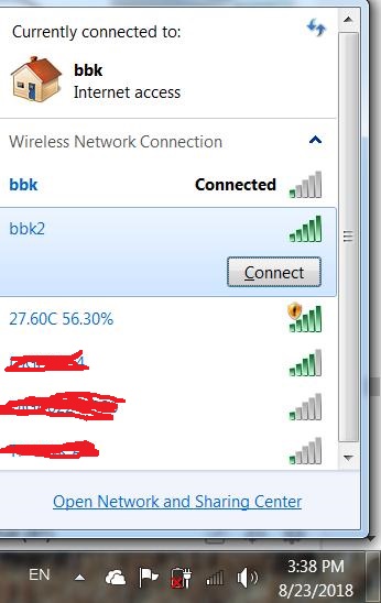
If you play with switches as me, with this configuration
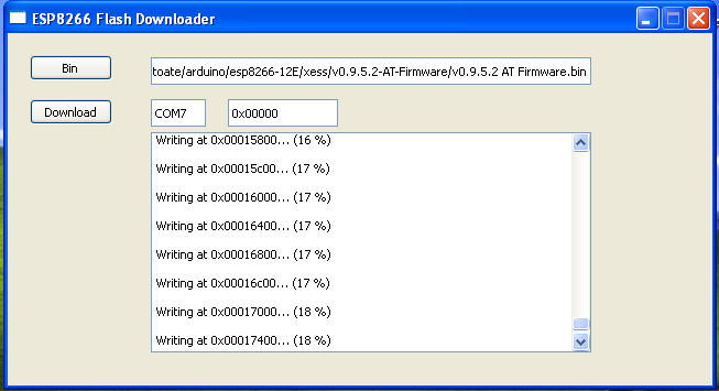
and pus ESP-RST button, firmware will be erased... and this sheild not work, is just a piese untill you reflash the ESP8266 chip.
I use info from article ESP8266: Reflash Dance! writted by Dave Vandenbout for classic ESP8266:
I tested an (retired now) WeMos D1 development board made with ESP8266EX microcontroller. About this board I found some info at https://www.wemos.cc/product
For easy use as other Arduino boards, is ok to see this picture:
Last project with this board is a Web Switch Control.
This sketch made a webserver using AJAX style (static page and just some datas is changes).
My sketch led_controlled_from_webpage.ino has some change line, but I use same password (1234), and my led is at GPIO5 (D15/SCL) and GND (I not put 220-470 ohms resistor limiter, but is more good to put). I use 8087 port, but you can change to 80.
After I tested about one mounth, I see some problemes, when wi-fi router is disconnected and reconnect.. so, I study but I give a tip from a collaborator, Mircea Craciun, who indicate my another post from ESP8266 forum.
I put an LED for wi-fi error at GPIO12 (D12/MISO) and GND.
At first start, after restart or if link between router and WeMos is broken, second led blink until link with wi-fi is ok. You can see in ESP8266 Switch control with autoreconnect to wi-fi network movie how WeMos D1 board is working.
At http://www.esp8266.com/wiki/doku.php?id=arduino-docs I found how I can use EEPROM memory from ESP8266EX microcontroller for store the state of led (ON or OFF) and number of good clicks (just for see how work the system).


 - 2nd step: ssearch ESP8266