As a beginner with model railroading I tested also DCC control using a custom locomotive.
My custom locomotive was make using just bogie from an old locomotive, adding DCC ready board and NEM652decoder.


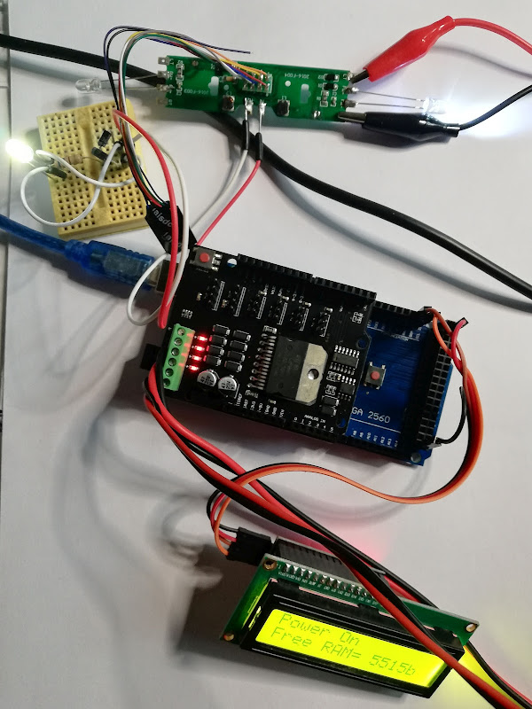
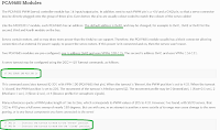
so, I used for as Command Station: Arduino Mega development board, a Motor shield, ESP8266-01 with logical level adapter, i2c LCD1602 (and than OLED) display + 4 servos connected at an expander board on i2c with 16 outputs using PCA9685 chip, using info from
- https://dcc-ex.com/get-started/wifi-setup.html
- DCC++Ex Web Throttle (https://dcc-ex.com/throttles/ex-webthrottle.html)
- Engine Driver Android app (https://dcc-ex.com/throttles/engine-driver.html)
I was interested to control servos (for future turnouts) so I used info from:
- https://dcc-ex.com/reference/software/command-summary.html

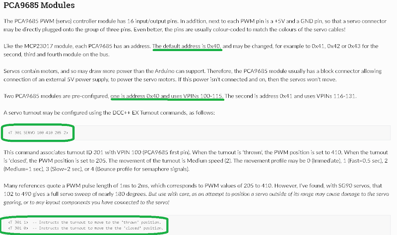
 So, for first servo (turnout), command is <T 200 SERVO 100 410 205 3>, where 200 is choose ID for turnout, 100 is VPIN (virtual pin for first servo connected at PCA9685), 410 is PWM number for throw (open) for SG90, 205 is PWM number for close position and 3 is slowest movement (0 is fastest movement).
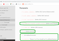
Base commands for turnouts in DCC++EX are:

and for SG90 servo:
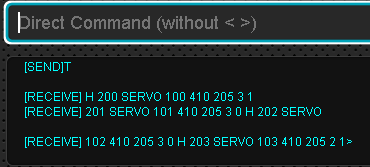
Easiest mode is to use web throttle (serial control)


For second servo (turnout), command is <T 201 SERVO 101 410 205 3>, where 201 is choose ID for turnout, 101 is VPIN (virtual pin for second servo connected at PCA9685), 410 is PWM number for throw (open) for SG90, 205 is PWM number for close position and 3 is slowest movement..

So, for third servo (turnout), command is <T 202 SERVO 102 410 205 3>, where 202 is choose ID for turnout, 102 is VPIN (virtual pin for third servo connected at PCA9685), 410 is PWM number for throw (open) for SG90, 205 is PWM number for close position and 3 is slowest movement .

So, for first servo (turnout), command is <T 203 SERVO 103 410 205 2>, where 200 is choose ID for turnout, 100 is VPIN (virtual pin for first servo connected at PCA9685), 410 is PWM number for throw (open) for SG90, 205 is PWM number for close position and 2 is medium movement.

Next step (mandatory) is to store this turnouts in EEPROM memory using <E> command

Base commands are:
- to throw (open) thefirst turnout

- to close the first turnout

When open Android "Engine Driver" I saw the turnouts defined

so I ca control the servos:
- all turnouts throw (open)


- first turnout closed, rest turnouts open


- all turnouts closed


You can see a video with control the turnouts with servo: 4 servo (turnouts) controlled by Arduino as DCC++Ex Station and Engine Driver app
Bibliography: