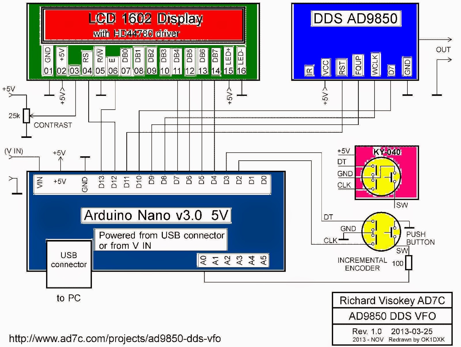
Base project is from http://www.ad7c.com/projects/ad9850-dds-vfo/
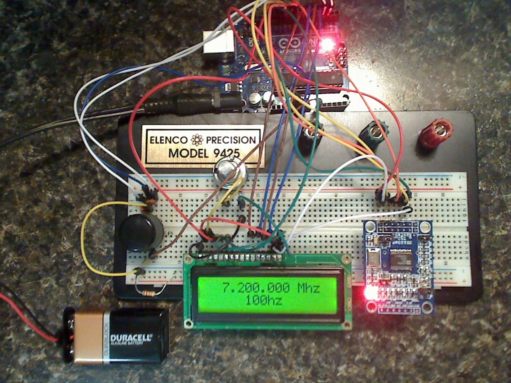
After I upload sketch and put oscilloscope I can see the square signal:


and sinus:


I made a frequencymeter with Arduino with info from http://interface.khm.de/index.php/lab/interfaces-advanced/arduino-frequency-counter-library/

My resuslts are:


I made a movie named Arduino AD9850 DDS + Arduino frequencymeter
I use this sketch for DDS with AD9850, Arduino and rotary encoder:
/*
Main code by Richard Visokey AD7C - http://www.ad7c.com
Revision 2.0 - November 6th, 2013
adapted sketch 1.2 - january 1st, 2015 - by Nicu Florica - http://www.tehnic.go.ro
http://nicuflorica.blogspot.ro/
http://arduinotehniq.blogsopt.com/
*/

// Include the library code
#include <LiquidCrystal.h>
#include <rotary.h>
#include <EEPROM.h>

//Setup some items
#define W_CLK 8   // Pin 8 - connect to AD9850 module word load clock pin (CLK)
#define FQ_UD 9   // Pin 9 - connect to freq update pin (FQ)
#define DATA 10   // Pin 10 - connect to serial data load pin (DATA)
#define RESET 11  // Pin 11 - connect to reset pin (RST)
#define pulseHigh(pin) {digitalWrite(pin, HIGH); digitalWrite(pin, LOW); }
Rotary r = Rotary(2,3); // sets the pins the rotary encoder uses.  Must be interrupt pins.
LiquidCrystal lcd(13, 12, 7, 6, 5, 4); // I used an odd pin combination because I need pin 2 and 3 for the interrupts.
int_fast32_t rx=7200000; // Starting frequency of VFO
int_fast32_t rx2=1; // variable to hold the updated frequency
int_fast32_t increment = 1; // starting VFO update increment in HZ.
int buttonstate = 0;
String hertz = "1 Hz";
int  hertzPosition = 6;
byte ones,tens,hundreds,thousands,tenthousands,hundredthousands,millions ;  //Placeholders
String freq; // string to hold the frequency
int_fast32_t timepassed = millis(); // int to hold the arduino miilis since startup
int memstatus = 1;  // value to notify if memory is current or old. 0=old, 1=current.

int ForceFreq = 0;  // Change this to 0 after you upload and run a working sketch to activate the EEPROM memory.  YOU MUST PUT THIS BACK TO 0 AND UPLOAD THE SKETCH AGAIN AFTER STARTING FREQUENCY IS SET!

void setup() {
  pinMode(A0,INPUT); // Connect to a button that goes to GND on push
  digitalWrite(A0,HIGH);
  lcd.begin(16, 2);
  PCICR |= (1 << PCIE2);
  PCMSK2 |= (1 << PCINT18) | (1 << PCINT19);
  sei();
  pinMode(FQ_UD, OUTPUT);
  pinMode(W_CLK, OUTPUT);
  pinMode(DATA, OUTPUT);
  pinMode(RESET, OUTPUT);
  pulseHigh(RESET);
  pulseHigh(W_CLK);
  pulseHigh(FQ_UD);  // this pulse enables serial mode on the AD9850 - Datasheet page 12.
  lcd.setCursor(hertzPosition,1);
  lcd.print(hertz);
   // Load the stored frequency
  if (ForceFreq == 0) {
    freq = String(EEPROM.read(0))+String(EEPROM.read(1))+String(EEPROM.read(2))+String(EEPROM.read(3))+String(EEPROM.read(4))+String(EEPROM.read(5))+String(EEPROM.read(6));
    rx = freq.toInt();
  }
}


void loop() {
  if (rx != rx2){
        showFreq();
        sendFrequency(rx);
        rx2 = rx;
      }

  buttonstate = digitalRead(A0);
  if(buttonstate == LOW) {
        setincrement();
    };

  // Write the frequency to memory if not stored and 2 seconds have passed since the last frequency change.
    if(memstatus == 0){
      if(timepassed+2000 < millis()){
        storeMEM();
        }
      }
}


ISR(PCINT2_vect) {
  unsigned char result = r.process();
  if (result) {
    if (result == DIR_CW){rx=rx+increment;}
    else {rx=rx-increment;};
      if (rx >=30000000){rx=rx2;}; // UPPER VFO LIMIT
      if (rx <=1){rx=rx2;}; // LOWER VFO LIMIT
  }
}


// frequency calc from datasheet page 8 = <sys clock> * <frequency tuning word>/2^32
void sendFrequency(double frequency) {
  int32_t freq = frequency * 4294967295/125000000;  // note 125 MHz clock on 9850.  You can make 'slight' tuning variations here by adjusting the clock frequency.
  for (int b=0; b<4; b++, freq>>=8) {
    tfr_byte(freq & 0xFF);
  }
  tfr_byte(0x000);   // Final control byte, all 0 for 9850 chip
  pulseHigh(FQ_UD);  // Done!  Should see output
}
// transfers a byte, a bit at a time, LSB first to the 9850 via serial DATA line
void tfr_byte(byte data)
{
  for (int i=0; i<8; i++, data>>=1) {
    digitalWrite(DATA, data & 0x01);
    pulseHigh(W_CLK);   //after each bit sent, CLK is pulsed high
  }
}

void setincrement(){
  if(increment == 1){increment = 10; hertz = "10 Hz"; hertzPosition=5;}
  else if(increment == 10){increment = 50; hertz = "50 Hz"; hertzPosition=5;}
  else if (increment == 50){increment = 100;  hertz = "100 Hz"; hertzPosition=4;}
  else if (increment == 100){increment = 500; hertz="500 Hz"; hertzPosition=4;}
  else if (increment == 500){increment = 1000; hertz="1 kHz"; hertzPosition=6;}
  else if (increment == 1000){increment = 2500; hertz="2.5 kHz"; hertzPosition=4;}
  else if (increment == 2500){increment = 5000; hertz="5 kHz"; hertzPosition=6;}
  else if (increment == 5000){increment = 10000; hertz="10 kHz"; hertzPosition=5;}
  else if (increment == 10000){increment = 100000; hertz="100 kHz"; hertzPosition=4;}
  else if (increment == 100000){increment = 1000000; hertz="1 MHz"; hertzPosition=6;}
  else{increment = 1; hertz = "1 Hz"; hertzPosition=6;};
   lcd.setCursor(0,1);
   lcd.print("                ");
   lcd.setCursor(hertzPosition,1);
   lcd.print(hertz);
   delay(250); // Adjust this delay to speed up/slow down the button menu scroll speed.
};

void showFreq(){
    millions = int(rx/1000000);
    hundredthousands = ((rx/100000)%10);
    tenthousands = ((rx/10000)%10);
    thousands = ((rx/1000)%10);
    hundreds = ((rx/100)%10);
    tens = ((rx/10)%10);
    ones = ((rx/1)%10);
    lcd.setCursor(0,0);
    lcd.print("                ");
   if (millions > 9)
   {
       lcd.setCursor(1,0);
      }
   else
   {
        lcd.setCursor(2,0);
   }
    lcd.print(millions);
    lcd.print(",");
    lcd.print(hundredthousands);
    lcd.print(tenthousands);
    lcd.print(thousands);
    lcd.print(".");
    lcd.print(hundreds);
    lcd.print(tens);
    lcd.print(ones);
    lcd.print(" MHz  ");
    timepassed = millis();
    memstatus = 0; // Trigger memory write
};

void storeMEM(){
  //Write each frequency section to a EPROM slot.  Yes, it's cheating but it works!
   EEPROM.write(0,millions);
   EEPROM.write(1,hundredthousands);
   EEPROM.write(2,tenthousands);
   EEPROM.write(3,thousands);
   EEPROM.write(4,hundreds);
   EEPROM.write(5,tens);
   EEPROM.write(6,ones);
   memstatus = 1;  // Let program know memory has been written
   lcd.setCursor(1,15);
   lcd.print("*");
   delay(500);
   lcd.setCursor(1,15);
   lcd.print(" ");

};

I made a movie with a preliminary test for DDS with AD9850 and TFT display with touch...
HI,
ReplyDeleteI repeated your project exactly one to one
but when i tried to program the Arduino
I get always the same error -
Rotary does not name a type.
Can you help me please?
George
I think you haven't rotary.h library... I'm right?
DeleteThank you for your source code. When I uploaded to AD9850 an error appeared stating no declaration for showFreq () ; What is your advice to correct this error? I am using an Aduino R3 uno CH 340 AT Mega 328P.
ReplyDeleteLooking forward to your reply.
Perry
I recompile the sketch on new Arduino Ide an d is ok.. I think you not copy entire sketch... please send me a print screen of errors
ReplyDeleteHi, I am building AD9850 based signal generator module, I used the above given code and schematic for frequency generation. I am able to read the frequency on LCD but I am not able to verify the same on CRO. i.e only one frequency is shown on CRO but change of frequency by rotating the rotary encoder is not shown on CRO, But on LCD it is visible. Please help asap.
ReplyDeleteHi, I am building AD9850 based signal generator module, I used the above given code and schematic for frequency generation. I am able to read the frequency on LCD but I am not able to verify the same on CRO. i.e only one frequency is shown on CRO but change of frequency by rotating the rotary encoder is not shown on CRO, But on LCD it is visible. Please help asap.
ReplyDeleteI dont understund exacttly your problem...
Deleteafter last changed fracquecy from rotary encoder Arduino wait 2 seconds and send new frecquency to AD9850....
// Write the frequency to memory if not stored and 2 seconds have passed since the last frequency change.
if(memstatus == 0){
if(timepassed+2000 < millis()){
storeMEM();
}
what is CRO ?
also with reference to my previous question, is it possible to update the frequency on DDS automatically? Like between 20Hz to 20kHz (in user defined steps) and feed it to arduino UNO and acquire and dsiplay the same on PC?? I am using simulink block in Matlab R2015a for analog read from arduino. So far very little success is being achieved. I will be grateful for your help in coding for the above problem statement.
ReplyDeletecro = cathode ray oscilloscope
ReplyDeletethx..
DeleteHello
ReplyDeleteI am not a professional coder but could build the generator about the instructions and working just fine. Somebody could help me out with a code wich stops the whole process if you not turning the rotary? I mean there is a sin wave on the amplifier what we hear but it could be so anoying so i would stop it automatically if you not turning the rotary but if you turnt it again you can hear again the sound (from start or from last frequency is whatever). I would use this setup for a chladnie wave.
thank you
I will try to help you, but I don't undertand exactly what you want to made.. please be more clear ...
Deletesorry i am not a native English speaker.
ReplyDeleteSo i will try it again :
First i just start the arduino + wave genarator with an amplifier to hear the sound of the wave.
Just set a sin wave with rotary to a frequency example 1000Hz
its a bit hurting your ears and anoying i would make the arduino program to stop automatically the wave and than alos we wont hear anymore the sound aswell (maybe set to 0Hz or set it to a very high frequency to not hear it) example after 3sec if i am not moving the rotary
than its silence until i start to move the rotary again.
Thank you for your help and i hope i was understandebla
I'm from Romania, so I'm not a native Eanglish speaker, like you ;)
DeleteAfter power on, you want 1000Hz 3 seconds, after that nothing? just rotate encoder to hear frecquency, but after you not rotate must off after 3 seconds?
Is not more easy to generate sound directly with Arduino at 1000Hz, and rorate a potentiometer who can change frecuency between 500 to 10000Hz, and after 3 seconds when you not rotate, sound stops?
Still not clear than sorry :D I am from Hungary next to you. So the process is:
Deleteits a chladnie wave generator. Its starts, you can chose any frequency from 100-1200 with the potentiometer and you can hear whatever you chose and also hear while rotating but after you are bored to "play" with this it would be so anoying if its just plays forever the last frequency so after nobody playing it should stop.
thinking of somthing like:
Deleteif (3sec passed, and the rotary at the same position) then digitalwrite frequency to 0HZ. if you rotate again the potenciometer it works again like before.
I understand, but now I haven't time for made changes in sketch... try to request help on Arduino forum or other forum..
DeleteI need waveform generator sketch for four step with four different fixed frequencies where the frequency wl not be shown on the lcd, just on lcd Will appear: step one, step two, step three, step four, and they will be changed by pressing the encoder. Please someone to help me. Thanks
ReplyDelete