I try more version, and now I present you a AC light dimmer with 2 push buttons for 16 steps and a alphanumerical LCD1602 display. I use 100W incandescent bulb at 230V/50Hz.
My schematic is:


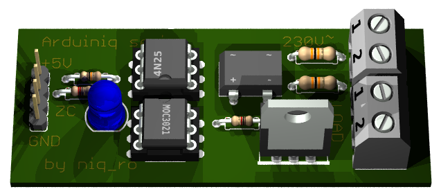
My handmade module is:


In my case, I have 16 steps of intensity of bulb:
- bulb is off (0%):

- 1st step (6%):

- 2nd step (13%):

- 3rd step (19%):

- step no.4 (25%):

- stept no.5 (31%):

- step no. 6 (38%):

- step no.7 (44%):

- step no.8 (50%):

- step no.9 (57%):

- step no.10 (63%):

- step no.11 (69%):

- step no.12 (75%):

- step no.13 (82%):

- step no.14 (88%):

- step no.15 (94%):

- last step (100%), bulb is at maximum:

My sketch is:
/*
AC Light Control
 Updated by Robert Twomey <rtwomey@u.washington.edu>
 Thanks to http://www.andrewkilpatrick.org/blog/?page_id=445
 and http://www.hoelscher-hi.de/hendrik/english/dimmer.htm
 adapted sketch by niq_ro from
 http://www.tehnic.go.ro
 http://www.niqro.3x.ro
 http://nicuflorica.blogspot.com &  http://arduinotehniq.blogspot.com
*/

#include <LiquidCrystal.h>
// use LiquidCrystal.h library for alphanumerical display 1602
LiquidCrystal lcd(13,12,11,10,9,8);
/*                                     -------------------
                                       |  LCD  | Arduino |
                                       -------------------
 LCD RS pin to digital pin 13          |  RS   |   D13   |
 LCD Enable pin to digital pin 12      |  E    |   D12   |
 LCD D4 pin to digital pin 11          |  D4   |   D11   |
 LCD D5 pin to digital pin 10          |  D5   |   D10   |
 LCD D6 pin to digital pin 9           |  D6   |    D9   |
 LCD D7 pin to digital pin 8           |  D7   |    D8   |
 LCD R/W pin to ground                 |  R/W  |   GND   |
                                       -------------------
*/
#include <TimerOne.h>           // Avaiable from http://www.arduino.cc/playground/Code/Timer1

volatile int i=0;               // Variable to use as a counter
volatile boolean zero_cross=0;  // Boolean to store a "switch" to tell us if we have crossed zero
int AC_pin = 3;                 // Output to Opto Triac
int buton1 = 4;                 // first button at pin 4
int buton2 = 5;                 // second button at pin 5
int dim2 = 0;                   // led control
int dim = 128;                  // Dimming level (0-128)  0 = on, 128 = 0ff
int pas = 8;                    // step for count;
// version: 4m7 (15.04.2013 - Craiova, Romania) - 16 steps, 4 button & LED blue to red (off to MAX)
// version: 7m3 (22.01.2014 - Craiova, Romania) - 16 steps, 2 button & LCD1602

int freqStep = 75;    // This is the delay-per-brightness step in microseconds for 50Hz (change the value in 65 for 60Hz)


void setup() {  // Begin setup
  Serial.begin(9600);
  pinMode(buton1, INPUT);  // set buton1 pin as input
  pinMode(buton2, INPUT);  // set buton1 pin as input
  pinMode(AC_pin, OUTPUT);                          // Set the Triac pin as output
  attachInterrupt(0, zero_cross_detect, RISING);    // Attach an Interupt to Pin 2 (interupt 0) for Zero Cross Detection
  Timer1.initialize(freqStep);                      // Initialize TimerOne library for the freq we need
  Timer1.attachInterrupt(dim_check, freqStep);
  // Use the TimerOne Library to attach an interrupt

 lcd.begin(16, 2); // set up the LCD's number of columns and rows:
 lcd.clear(); // clear the screen
 lcd.setCursor(2, 0); // put cursor at colon 0 and row 0
 lcd.print("16 steps AC"); // print a text
 lcd.setCursor(0, 1); // put cursor at colon 0 and row 1
 lcd.print("dimmer for bulb"); // print a text
 delay (3000);
 lcd.clear(); // clear the screen
 lcd.setCursor(1, 0); // put cursor at colon 0 and row 0
 lcd.print("this sketch is"); // print a text
 lcd.setCursor(1, 1); // put cursor at colon 0 and row 1
 lcd.print("made by niq_ro"); // print a text
 delay (3000);
 lcd.clear(); // clear the screen
}

void zero_cross_detect() {
  zero_cross = true;               // set the boolean to true to tell our dimming function that a zero cross has occured
  i=0;
  digitalWrite(AC_pin, LOW);
}

// Turn on the TRIAC at the appropriate time
void dim_check() {
  if(zero_cross == true) {
    if(i>=dim) {
      digitalWrite(AC_pin, HIGH);  // turn on light
      i=0;  // reset time step counter
      zero_cross=false;    // reset zero cross detection
    }
    else {
      i++;  // increment time step counter
    }
  }
}

void loop() {
  digitalWrite(buton1, HIGH);
  digitalWrite(buton2, HIGH);

 if (digitalRead(buton1) == LOW)
   {
  if (dim<127)
  {
    dim = dim + pas;
    if (dim>127)
    {
      dim=128;
    }
  }
   }
  if (digitalRead(buton2) == LOW)
   {
  if (dim>5)
  {
     dim = dim - pas;
  if (dim<0)
    {
      dim=0;
    }
   }
   }
    while (digitalRead(buton1) == LOW) {  }
    delay(10); // waiting little bit...
    while (digitalRead(buton2) == LOW) {  }
    delay(10); // waiting little bit...


  dim2 = 255-2*dim;
  if (dim2<0)
  {
    dim2 = 0;
  }

  Serial.print("dim=");
  Serial.print(dim);

  Serial.print("     dim2=");
  Serial.print(dim2);
  Serial.print("     dim1=");
  Serial.print(2*dim);
  Serial.print('\n');
  delay (100);
 lcd.setCursor(2, 0); // put cursor at colon 0 and row 0
 lcd.print("power is "); // print a text
 lcd.print(100-100*(255-dim2)/255);
 lcd.print("%    "); // print a text
 lcd.setCursor(1, 1); // put cursor at colon 0 and row 1
 lcd.print("dim. level="); // print a text
 lcd.print(dim);
 lcd.print("  "); // print a text
}
NOTE: For 60Hz must change
int freqStep = 75;
in int freqStep = 65;
!
I made 2 movies with this AC light dimmer:
- ac light dimmer with Arduino (XVII)You can made PCB using lay file from http://arduinolab.pw and you can download Sprint Layout Viewer for open this file...
Hi first of all congratulations for your work, one question, i follow your design but my electrical network its 120VAC/60HZ i dont know if this is a problem, but when i load my code and press my buttons the bulb doesnt turn on only the led but when the dim2 its 239 the bulb turn on at 100% im using ltv4n35 i dont know iwhats the problem if you can help me please.? thank you.
ReplyDeleteNot sure if it is the problem but with 60 hz u have an 8.33 ms between the zero crosses as opposed to 10ms for 50hz.. so yr steps need to be smaller as 128*75=10.000 us=10ms. For 60 hz u need to Chang freqstep=75 I to 65.
DeleteAlso, the two 91 k resistors ate probably way too large for 120 volt. Try 33k
DeleteI am the author of the arduinodiy article referred to https://arduinodiy.wordpress.com/2012/10/19/dimmer-arduino/
Deletetwo 91k are definitely too large, even for 230, let alone for 120.
Using 33k is a good start but for 120 Volt, you should even go lower.
The width of the zerocrossing pulse increases with a high resistor value, leading the interrupt to take place way before the actual zerocrossing. 2x 15k or one 33k might be a good value
in my country power supply is 230V/50Hz.. for 60Hz freqstep=65.. see http://playground.arduino.cc/Code/ACPhaseControl and https://arduinodiy.wordpress.com/2012/10/19/dimmer-arduino/
ReplyDeleteSir where can i download the schematic above?
ReplyDeleteIs it possible to drive inductive load like a transformer with this circuit ?
ReplyDeleteyes, just add few components, see http://www.sonelec-musique.com/electronique_theorie_triac.html
Deletehello great work, when i upload the code the button1 turns the light directly to 100% but the code says power is 0% to it, the schematic is wired like yours however i used a MOC3031 zero cross, and an SC141 triac as they were the only ones available at my electronic store that could manage the power. i am on 120VAC 50hz
ReplyDeleteput MOC without zero cross detector...
DeleteWhat if I'm using 60W incandescent light bulb for this project?
ReplyDeleteI use 100W bulb and is ok, so if you use 60W bulb is more ok :D
Deleteok :D Thanks.By the way, can i get the list of component for this project ? because i'm trying to make this work for my Final year project.
Deleteprint on paper the schematic ang go to shop ;)
Deleteok :) Thanks
DeleteCan i test the dimming circuit by using the electronic breadboard ? ( Before i make a PCB circuit )Can the breadboard handle the higher voltage ?
yes, you can test... see in my pictures ;)
Deletewhat is the size for the PCB board circuit when you are using Eagle PCB software to design it ?
DeleteAfter I connect all the component and circuit , why the light bulb didn't light up ? I input the value then nothing happen.
ReplyDeleteYou respect 100% the schematic?
DeleteI change the 4N25 to h11aa1 , moc3040 to moc 3021, then all the component are the same, I was using breadboard to test this circuit, have current flow but even the LED light didn't light up
Deleteparallel few bulbs can connect ??
ReplyDeleteThanks for the tutorial is very good, congratulations.
yes, you can put more bulb lamps, but toal power must be less than 100-200W for normal use, but is you put heatsink on triack, can put more power...
Deletethanks for the reply
DeleteCan I change the 4n35 opto to 4n26 ? And moc3040 change to moc3021 ?
ReplyDeleteI also show the led didn't light up after I switch on the supply
you can use any opto for zero cross detector (4N35, 4N26, etc), but for control the triac must use MOC with out zero cross detector...
DeleteWhen I switch on the supply , I only see the light bulb bright a bit and dim, even my led bulb at moc3021 there didn't light up , what is happen sir? my supply is 240vac 60hz, is the 91k resistor suitable ?
ReplyDeletetry first excample from https://arduinodiy.wordpress.com/2012/10/19/dimmer-arduino/
Deleteuse 33k on each leg instead of 91K
DeleteSir, are you using the moc3021 with zero crossing detector? my led doesn't light up after I switch on the supply
ReplyDeleteif you see in schematic in s MOC3040.. in photo is MOC3020.. all without zero cross detector... so?
DeleteYes, I understand .but sir,I have follow all your schematic connection , and still nothing happen ,even the led don't light up .
Deletewrite a mail to me (nicu.florica@gmail.com) with photo...
Deleteyou change MOC3021 with MOC3020 or MOC3040 ?
Good morning, I built this project and wanted to create a steady fade from 0 to maximum intensity with a linear function, how could I do? I tried with the map function and a variable that increases by 1 but the lamp trembles. Thanks so much
ReplyDeleteyou want fade? see base article from https://arduinodiy.wordpress.com/2012/10/19/dimmer-arduino/ ;)
Deleteyou can change to
Deletevoid loop() {
for (int i=5; i <= 128; i++)
{
dimming=i;
delay(10);
}
for (int i=5; i <= 128; i++)
{
dimming=133-i; // 128+5=133..
delay(10);
}
} // end mai loop
Hi, interesting work. Is it possible to use with out a push button switch, and instead using a signal pulse from the arduino through the circuit to dim the light bulb? Looking forward to your reply.
ReplyDeleteI don't understund what you want to change... please explain more detailed...
DeleteI am currently finding a way in such that i can control the dimming of the light bulb just by programming the arduino. For instance: i wish to set the light bulbs brightness by 40% from the laptop.
DeleteThe bulb just blink at the connecting and disconnecting the cable from power socket, it doesn't lighting. What can i done wrong? I have Arduino Nano copy from China.
ReplyDeleteyou use exactly pins as in my schematic?
ReplyDeletealso, try test sketch from: https://arduinodiy.wordpress.com/2012/10/19/dimmer-arduino/
Can We control the speed of AC Fan ?
ReplyDeletesee russian article from http://www.motor-r.info/p/blog-page_19.html ;)
DeleteHi,
ReplyDeleteWould it be possible for you to share your Eagle PCB files? I would like to get a board manufactured for my personal use (not commercial use). :-)
Feel free to e-mail me at: cykey [at] live [dot] com
Thank you!
David.
hi .
ReplyDeletei tried to create the same circuit. but i am not be able to understand that in the diagram the B1 must be bridge rectifier circuit (with transformer) isn't it?
also in your actual image can you tell me what component you have used on the position of B1. IT WILL HELP ME A LOT TO COMPLETE THE CIRCUIT. thanks in advance.
yes, B1 is rectifier for max.1A/400V, but you can use 4 diodes 1N4007
Deletehi . I really appreciate your reply on my post.
DeleteI am using DB107 in the place of B1.
I am very sorry for asking you this question again ( electronics is really not my field) . the input to B1 or the bridge is directly 220v AC or AC input from the transformer.
directlly at 220V AC.. in schematis in not any transformer
DeleteNicule!!! Saluty , Imi spui te rog daca se poate controla turatia la un motor de masina de spalat cu acest dimmer si daca motorul va avea aceeasi forta si care ar fi schema electrica cea mai simpla.
ReplyDeleteCa vreau sa fac un programator de masina de spalat ca am o masina stricata si nu mai gasesc programator pt ea. Email-ul meu Aladinx36@yahoo.com
salut... nu am timp sa testez, dar am gasit ceva pe un site rusesc, merita incercat: http://www.motor-r.info/p/blog-page_19.html
DeleteMersi frumos , exact ce cautam.
Deletehi
ReplyDeletecan this be use for more than one line (bulb or light)at same time and control individually
what need to be done in the program code or the diagrams or the schem.
ReplyDeletefinally it very cool and will help reducing the power bills
good job
Hello! I'm redoing your project. I encountered a small problem. The lights on the lights are very weak. It seems I can not control the 100W bulb, it does not have any change, the lamp is off. Give me a fix. Thank you
ReplyDelete"Res 91k ohm" is 2W?
ReplyDeleteCan i use 'Res having another Watt' like 1/4W or 1/2W?
Please answer me..
put 1/2W or 1W
DeleteI have 1K '1/4W'. The 'RES 1K ohm "1/4W"' can work on this module? Can i use it? Isn't it dangerous?
ReplyDelete1k instead 91k ?????????
ReplyDeletein the happy case 1k will burn.. in usual case you distroy all: optocoupler, Arduino, PC...
No I mean, I have RES
ReplyDelete[RES1 : 220 ohm , 1/2W
RES3 : 10K, 1/2W
RES4, RES5 : 91K, 1W
RES2 : 1K , 1/4W (You say "put 1/2W or 1W", but i have 1/4W in the 1K RES case. Can i use this one? that is what I want to ask)]
You say "Put 1/2W ot 1W", I have 1/2W or 1W on the 91K, 220, 10K cases.
but just one thing(1K) is 1/4W, Is it OK?
is ok
ReplyDeleteThis comment has been removed by the author.
ReplyDeleteHello my friend im from Mexico and i use a similar dimmer but in the code i use an extra library available in github.com called "Dimmer" i say this with the intention of making things easier, thanks for this contribution, GOOD JOB
ReplyDeleteHi Sir!
ReplyDeleteCan I control the power of triac through Programming?
hello, nice work . thanks for your time . could i know what the exact name for B1 in schematics?
ReplyDeleteB1 is general rectifier bridge (1A/400V), it can be change with 4 diodes 1N4007...
Deletemas sudah kucoba tapi ko gbsa ya mas? aada rangkaiannyaa ga mas?
ReplyDeletemy project can't working, do you have a circuit picture?
Deleteare you kidding? you have all schematics and program in article...
DeleteHello led circuit did not light. I used 100k instead of 91 k. This could be the reason. Can I use 100k instead of 91k?
ReplyDeletei made the same circuit with the same components and it's not working i don't know why
ReplyDeleteyou must use exactly pins like in my schematic... also test sketch from https://arduinodiy.wordpress.com/2012/10/19/dimmer-arduino/
DeleteCan you please share your eagle schematic?
ReplyDeletefor me is an old experiment... I will search the Eagle file, but I don't think I find... in the past the harddisk with with my projects was broked... but I will search
Deletehi, I find lay file for this pcb at http://arduinolab.pw/index.php/2015/12/01/setevoj-dimmer-upravlyaemyj-arduino/
DeleteLAY file is not for Eagle software.. is for Sprint-Layout.. you can download a viewer from https://www.softpedia.com/get/Science-CAD/Sprint-Layout-Viewer.shtml
Is it possible to control an ac fan with this circuit?
ReplyDeletethis diagram is for resistive load (bulb in this case), see MOC datasheet to find diagram for inductive load..
DeleteThank you for posting this excellent information..it is very useful to me..!
ReplyDeleteClick here:
Light Control Sensor in Mumbai
Hi
ReplyDeleteThank you for this project.
What is the B1 in your schematic, and what can I replace 91 k ?
B1 = bridge rectifier for 400V 1A (also can be replace with 4 pcs of 1N4007).. 91kΩ resistors can be replaced with 82kΩ..100kΩ resistors 0,4W) see also https://arduinodiy.wordpress.com/2012/10/19/dimmer-arduino/
DeleteThank you .can I use in Esp8266?
ReplyDeleteno, just Arduino Uno, Nano
DeleteWhat can I do to work in esp ?
DeleteAnd what is zero crossing signal out in this board?
ReplyDeleteand in the esp8266 where do I connect ?
please read the article from https://www.learningelectronics.net/circuits/dimmer-with-mosfet.html and also http://nicuflorica.blogspot.com/2015/04/variator-de-tensiune-pentur-bec-cu.html
ReplyDeleteHi, thanks for your project.
ReplyDeleteI have a problem.
first, I replaced 91 k to 100 k and bridge rectifier to four 1n4007.
Second, I wrote a PWM signal with micropython on the Esp8266 module.
So, I did your project, but the lamp turns on 100%. The lamp turns on 100% and turning it on or off, the signal switch does not work, and when the lamp is turned on, the small LED has very little brightness. Is this problem related to the 100 kilo resistance that I chose, or does it not work at all because I used this module? If it is from the module and I replace it with Arduino UNO, will it work?
Thank you.
for PWM control try this: https://github.com/tehniq3/AC-light-dimmer-with-mosfet
DeleteThank you. I want to use a LED lamp to replace an Incandescent lamp. What can I do for it?
Delete