Total Pageviews

Thursday, March 3, 2022

Arduino automatic model train

original article

   As a noobie with the model train system and because I haven't too much free space for test with big railways, I search for an automatic model train system, where it used IR module for define frake momment (stop position is not instant, as in rea case, if push brake pedal and car stop is after few meters).

    First I found the video I Made an Automated Model Train With An Arduino! where it used direct control (DC voltage with normal or reversed polarity). I tested manually the functionality of the system with my adapted sketch as in video Automatic Model Train (test)

After that, I found article Back-and-forth train control by Arduino with IR sensor

with PWM control for speed, so I adapt the sketch (my sketch) and made a first test with push a carriage push by me, to see how system work, as in video Automatic Model Train (test 2)
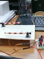
   Finally, I added L298 H-bridge module as in schematic
    First video is Arduino automatic model train

and second (with an oscilloscope on railway power) is Arduino automatic model train (2)


5-March-2022
    After I clean and greased an old Fleischmann 1966 as in movie 1966 Fleischmann 1306 Shunter: O&K MV9 - Bringing it back to life I make a new video named Fleischmann 1966 on Arduino automatic model train.
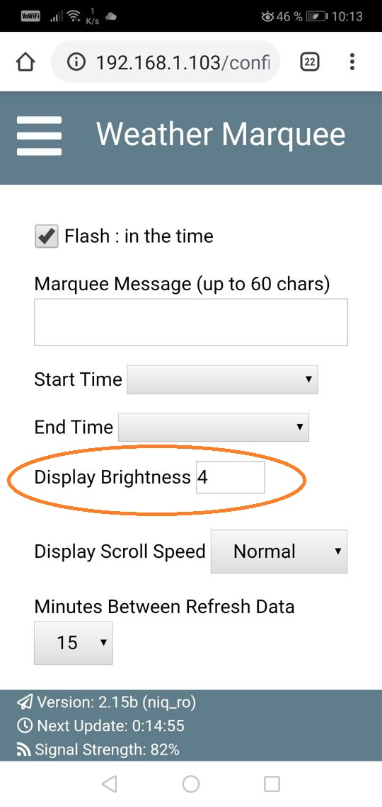
   PS: Improved sketch is controlled_model_train_1b.ino where it used for start PWM at 105 (aprox. 40%) not 0, remain maximum at 255 from 255 (100%). This mode to start the loco is useful for old DC motor.
   In next image you can see how automatic system for control the train ("loco") works:
   If train go forward, speed is constant, at maximum, if IR module 2 is actuated, speed decrease slow until train stop. After a small pause, train go backward, with speed increase from zero to maximum, and than IR module 1 is actuated, speed decrease slow to until train stop. Again, after a small pause, train go forward and cycle is repeated, as in next image:

Thursday, February 24, 2022

Automatic Railway Crossing system

original article


   `A schematic for an automatic railway crossing system:

I wrote a sketch for control 2 servos, warning ligts and sounds: doublebarriers_5.ino. As any Arduino fans knows, sounds and servo (using Tone and Servo libraries) not work simultanieous, but I used a trick, I activate servo when I want movements, deactivate the servo when I need sounds.

   When any IR sensor modules is actuated (LOW level) servos close the gates, red leds flash and speaker sound as in video double barriers with sound and lights (4)
    When railway is free gates are open, white led flashing.

   As I presened in previous post, Dragos (albasete) test sketch for real diorama, so:
  - barriers:
- warnings (sounds)

Railway Crossing system with manual control

original article


   I'm beginner as railways diorama, but I want to help the passionate peoples.

   First project with railway crossing system was for a manual control. 

   System control 2 servos with warning lights and sounds.

   Test schematic is

and program (sketch) is doublebarriers_3a7.ino.
    Real system created by my is on breadboard:
but Dragos (albasete) work more professional:

   I uploaded a short video named double barriers with sound and lights

Monday, April 20, 2020

Flashing led without delay

   I found another solution to made flashing led without delay than example from arduino IDE
   My solution is to use also millis() function but in other style. Millis() function count time from power up the Arduino (microcontroller)
   I use another variable, to made time from power up in seconds.After that I use rest function (%), for odd number led is on, for even number led is off. For example: 7%2=1 => led on, 8%2=0 => led off.
  You can see a simple mobvie with this style for control a led:
   I wrote 2 simple sketches: blink_wo_delay.ino and blink_wo_delay2.ino with same effects but little changes as commands.
  

Saturday, April 18, 2020

Consumption measurement for MAX7219 32x8 led display

   For measure the consumption for display made with 4 8x8 led modules drived by MAX7219. I use clock presented in article named ceas animat complex cu date de pe net, whitch use just a development board WeMos D1 Mini and display with 32x8 leds.
   Schematic for a module with 8x8 leds is:
Leds are controlated through muplexing system, so consumption is low.
    First, I removed the display for measure the resistor control for consumption:
I used also a microscope:
Value is 103, so is 10kohmi. You can ckech using an online calculator:
   My display is powered at 3.3V, but I also made measurements at 5V.
   I chose this clock because it can be controlled from a local web page and it's easy to change the intensity.
   We have selected the intensity at 0, the one commonly used at night or when it is cloudy outside and the average consumption is 16mA at 3.3V and 28mA at 5V:
   I selected the intensity at 4, the one commonly used during very bright daytime and the average consumption is 46mA at 3.3V and 66-73mA at 5V:

Friday, April 17, 2020

Bidirectional detection with ultrasonic sensors

   I will made a box with 2 doors and system need to detect movement so I tested a simple system with Arduino board and 2 ultrasonic sensors (HC-SR04).
   I used info from an old project (made a 7 yesrs ago)
   New test schematic is
   My program is bidirectional_detection_ultrasonic.ino and if any sensor detect an object bellow 25cm led is turned on for 3 seconds.
   I made 2 video with this system:


Tuesday, March 17, 2020

i2c LCD1602 drived by STM32F103C

 
   I wanted to use STM32F103 instead Arduno Mega for a radio with TEF6686 (see details at https://nicuflorica.blogspot.com/2020/02/radio-cu-tef6686.html).
   First, I tested classical sketch named i2_scanner but I received no device or error at all adresses beginning with 0x01.
   I search on internet and I found an interesting article STM32 I2C SCANNER. Because informations from there are too much and must read carefully, I change directly Arduino mega with STM32F103. I saw logo info on display and than nothing. I realised STM32 send correctly i2c comands to device, ut not understand messages from any device. LCD1602 (or LCD2004) need just commands, so can be used.
   I tested with LCD1602 powered from external 5V and STM32 board with 3.3V fron USB-FTDI interface or through USB using internal voltage regulator.
   Schematic is as in article from https://controllerstech.com/i2c-lcd-in-stm32/
    I made i2c LCD1602 drived by STM32F103C movie using STM32F103_i2c_LCD1602.ino sketch: