Total Pageviews

Saturday, June 1, 2019

Sending and Receiving Multiple Text Fields from Arduino in a Single Message

   For some applications we need to send numbers (integer or not) from one Arduino to another Arduino, fo example, is easy to read one or more analog inputs with Arduino and sent to ESP8266 or Nodemecu/Wemos board to publish on IoT server or local webpage. ESP8266 hase just one analog input and is more complicated to use electronic switch to comute for have multiple inputs.
   I test with simple schematic, using SerialSoftware to use D2 and D3 pins:
  I use info from Arduino Cookbook by Michael Margolis and extract info for use 2 Arduino boards, one as sender and second as receiver. Also first Arduino code the message before sending and second Arduino receive and decode the mesage.
   First, I send 3 integer number as in original article using tx_1.ino for fixed numbers or tx_1a.ino for random numebers. For receiver I use rx_1.ino sketch.
  I made Multiple Text Fields in Single Message using Arduino movie to see hwo system work.
   For send a temperature (as -23.50C or +23.50C), a state of a sensor (0 or 1) and a procentage (0 to 100), I use some calculus tricks, for example, I multiply the temperature value with 10 and use integer value, for negative temperature consider a number 1 for sign (and zero for positive) and send multiplied value added at state of sensor, extra send procentage value.
   For example, if temperature is +2.4 degree Celsius, state of sensor is 1 and procentage is 17%, first Arduino will send:
- first numeber is 24 (2.4*10)
- second number is 1, because temperature is positive and sensor is active: 0*10+1
- third number is 17.
   If second Arduino receive 119,11,39 return values are:
- temperature is -11.9 degree Celsius, because 119/10 = 11.9, sign is minus because 11 = 1*10 + 1
- sensor is activated becuse 11 = 1*10 + 1
- level of water is 39%.
   I made Multiple Text Fields in Single Message using Arduino (2)
using tx_2.ino sketch for transmiter and rx_2.ino.

Saturday, April 20, 2019

Delay off system using millis()

my original article

    In simple Arduino projects you can use delay command for have few seconds a led on and after that off, but in in this time program is halted. If you use millis() function, Arduino can execute other tests in program, not halt...
   In Arduino IDE program you cam find sketch named BlinkWithoutDelay
  In article Using millis() for timing you can find a good explanations
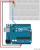
   I use this schematic for first test, using a push button and pull-up resistor on input
   If you upload delay_button.ino sketch, you will see next cases:
- standby state, led off:
- push buton, led off
- instantaneous, led on, time defined in sketch
- standby state, led off, again, waitting push button.
because I write the sketch using this chart
In Serial Monitor, you can see
   I change button with infrared module, schematic is
   For module sensor with normal state logic output (LOW in standby and HIGH when is triggered) sketch is delay_sensor.ino
and if you use other sensors with negative state logic output (HIGH in standby and LOW when is triggered) sketch is delay_sensor1.ino
    I made movie named delay off using millis()
    For this sketch(es), states are:
- stanfby, led off
- sensor is triggered, led is instant on
- led is on few seconds (selected in sketch), led is on
- after few seconds (selected in sketch), led is off
Also, in Serial Monitor, you can see the states:

Saturday, April 13, 2019

Simple alarm system with Arduino

original article
   A simple system alarm can be made with Arduino board, a sensor module (sound, PIR, Doppler, etc) and 2 switch or remote control.
   Base schematic is
If use buttons (switches) for control alarmsystem_0.ino is use without change
but is use remote control (singnal in HIGH) must changed in
Also, if sensor is like mine (infrared sensor) sketch is without change
but it easy to change in
for negative logic comand (active in LOW).
    After powered the system, alarm is in stand-by
and after push ON button (or button from remote control), alarm is in waitting mode
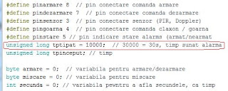
If sensor is activated, sound (yellow led in my case) is intermittently powered 10 second or more, depend value from here
   You can see 2 video:
20.04.2019
   I add a new movie with this alarm system using RCWL-0516 Doppler (radar) sensor (this sensor was tested a few time ago an posted at http://nicuflorica.blogspot.com/2018/02/senzor-de-miscare-tip-radar-doppler.html). 
   Default sketch is for power off the alarm system
but you can change to be armed after powered up dthe alarm system

Unidirectional Communcation between 2 Arduino boards

original article

   I want to send many commands using just 1 wire (and ground) so I use 2 Arduino boards.
   Base schematic for unidirectional communcication between Arduino boards is
and you can test this simple mode communication using info from article Tech Thurday #005: Arduino to Arduino Serial Communication.
   For sender (transmiter) I use a keypad with LCD1602 shield (see https://www.dfrobot.com/
This shield has the schematic
   Test schematic is
and sketch for transmiter is transmiter_v0.ino and sketch for receiver is receiver_v0.ino.
   If you have v.1.1 shield you must have
and for v.1.0
   I made Unidirectional Communication between 2 Arduino boards
  The states for this system are:
- all button are free (not pushed)
- if you push SELECT button
if you push LEFT button
if you push RIGHT button
if you push UP button
if you push DOWN button