Total Pageviews

Saturday, October 18, 2014

Weather station with Arduino Due on 2.2" TFT display

Note: This article is a rearrangement of article from http://arduinotehniq.blogspot.ro/2014/09/arduino-due-and-22-tft-display-with.html

   A usual weather station for domestic use must give us information about temperature and humidity, but a good weather station give us information about pressure, too.
   I design a weater station with 2.2" TFT display with ILI9341 driver.
 I did several experimets with Arduino Uno, then Arduino Mega and my conclusion is that development board are too slow for this display; so, I change classical Arduino board with next step, for me, Arduino Due.
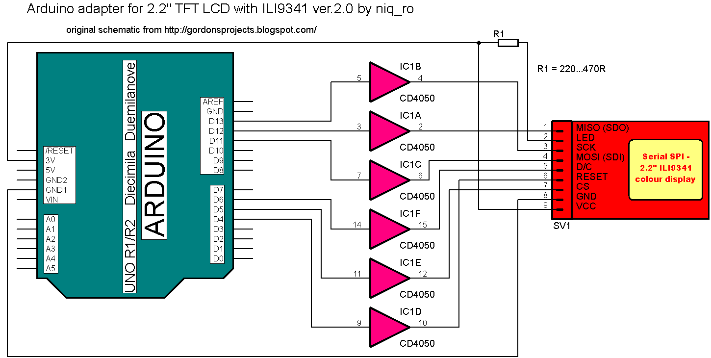
   Arduino Due works with 3.3V logical level like ILI9341 driver, so in schematic we not need the logical level convertor (eg CD4050) from 5V to 3.3V as in case use Arduino Uno or Mega.
   For control the colour display with ILI9341, I use graphical library named ucglib, derivated from u8glib library for monochrome graphical display.
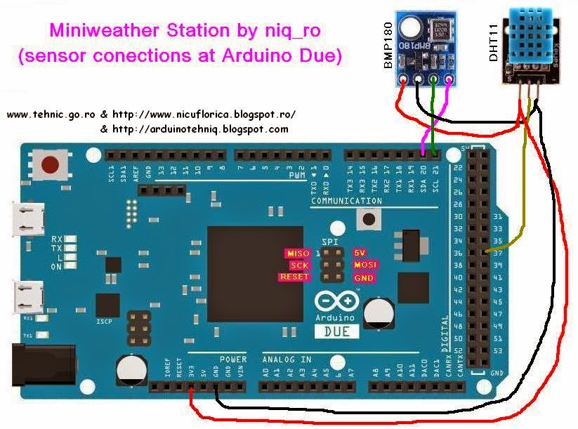
   I decided to use BMP180 sensor for give information about temperature and pressure & DHT11 sensor for give just humidity value, because is not accurate at temperature reading.
   My schematic for sensors at Arduino Due is:
   In my case, real ensemble is:
   For upload a sketch in Arduino Due must install a  new version of Arduino IDE, named 1.5.7 Beta (in future, version will be changed, but now 1.5.7 Beta is current version).
   For DHT11 sensor must use a new library compatible with Due, I found in a article named  Class for DHTxx sensors (xx = 11-21-22-33-44) and for BMP180 I use  Adafruit-BMP085.
   I write some original sketches for this weather station, and last is:
/*
original sketch by niq_ro from http://nicuflorica.blogspot.comhttp://arduinotehniq.blogspot.com using ucglib library
version for 2.2" TFT with ILI9341  - 2014.07.29, Craiova - Romania
use Universal uC Color Graphics Library from https://code.google.com/p/ucglib/
*/
#include <SPI.h>
#include "Ucglib.h"
//Ucglib_ILI9341_18x240x320_HWSPI ucg(/*cd=*/ 6 , /*cs=*/ 5, /*reset=*/ 4); // at Uno
//Ucglib_ILI9341_18x240x320_HWSPI ucg(/*cd=*/ 26 , /*cs=*/ 24, /*reset=*/ 22); // at Mega
//Ucglib_ILI9341_18x240x320_SWSPI ucg(/*sclk=*/ 52, /*data=*/ 51, /*cd=*/ 26 , /*cs=*/ 24, /*reset=*/ 22); //at Mega
//Ucglib_ILI9341_18x240x320_SWSPI ucg(/*sclk=*/ 76, /*data=*/ 75, /*cd=*/ 26 , /*cs=*/ 24, /*reset=*/ 22); //at Mega
Ucglib_ILI9341_18x240x320_HWSPI ucg(/*cd=*/ 26 , /*cs=*/ 24, /*reset=*/ 22); //at Mega or Due
/*

Due  |Mega | Uno | TFT - ILI9341
----------------------
D22  | D22 | D4  | RESET
D24  | D24 | D5  | CS
D26  | D26 | D6  | D/C
 ?   | ?   | LED (via 220 ohms resistor at 5V)
MOSI | D51 | D11 | MOSI
MISO | D50 | D12 | MISO
SCK  | D52 | D13 | SCK
-----------------------------
with CD4050 adapter or 10k resistor, power supply and logical levels is 3.3V
schematic: http://nicuflorica.blogspot.ro/2014/07/afisaj-grafic-color-qvga-de-22-cu.html
*/

#include <dht.h> 
// from http://playground.arduino.cc/Main/DHTLib
dht DHT;

// https://github.com/adafruit/Adafruit-BMP085-Library
#include <Wire.h>
#include <Adafruit_BMP085.h>
Adafruit_BMP085 bmp;

float t1, t2;
float t10, t20;
float t11, t21;
float t12, t22;
float t13, t23;
int h11, h12;
int p1, p2;

void setup() {
delay(1000);
bmp.begin();

ucg.begin(UCG_FONT_MODE_TRANSPARENT);
ucg.clearScreen();
ucg.setFont(ucg_font_ncenR14r);
ucg.setColor(255, 0, 255);
ucg.setColor(1, 255, 0,0);

  ucg.setRotate90();
  ucg.setColor(255, 255, 255); // culoare alba
  ucg.drawFrame(0,0,320,240); //   
  ucg.setFont(ucg_font_courB24); // 20 pixel height
  ucg.setColor(255, 0, 0); // culoare rosie
  ucg.setPrintPos(60,30);
  ucg.print("Ministatie");
  ucg.setColor(0, 255, 0); // culoare verde
  ucg.setColor(0, 255, 0);
  ucg.setColor(0, 0, 255); // culoare albastru
  ucg.setPrintPos(17, 60);
  ucg.print("meteo cu DHT11");
  ucg.setPrintPos(55, 90);
  ucg.setColor(5, 255, 0); // culoare verde
  ucg.print("si BMP180");
  ucg.setFont(ucg_font_fur17r); // 17 pixel height
  ucg.setColor(255, 255, 0); // culoare galbena
  ucg.setPrintPos(25,120);
  ucg.print("ecran grafic 2,2'' (5,6cm)");
  ucg.setFont(ucg_font_courB24); // 20 pixel height 
  ucg.setColor(0, 255, 255); // culoare bleo
  ucg.setPrintPos(10,150);
  ucg.print("QVGA cu ILI9341");
  ucg.setColor(255, 0, 255); // culoare mov
  ucg.setPrintPos(20,180);
  ucg.print("versiune 4.4.0");
  ucg.setFont(ucg_font_fur17r); // 17 pixel height
  ucg.setColor(255, 255, 255); // culoare alb
  ucg.setPrintPos(60,210);
  ucg.print("realizat de niq_ro");

delay(5000);
ucg.clearScreen();
t13=40.0;
h12=40.0;
p2 = 900;
}

void loop() {
 // BMP180 part 
 int p1 = bmp.readPressure()/101.325;
 p1 = p1 * 0.760;
     
 // DHT11 part
 int chk = DHT.read11(37);
 delay(1000);
// timeout;
 int h11 = DHT.humidity; 
 if (DHT.humidity < 0) h11 = 0;

// BMP180 part 2
t12 = bmp.readTemperature();
int t15 = t12;
float t16 = 10*t15;
t16 = t16/10;

t16 = t12;
if (t16 != t13) 
{
temperaturi(t16, t13, 20, 0); // temperature, old temperature, x,y
termometre(t16, 20);
}

if (h11 != h12) 
{
// umiditate(h11, h12, 115, 90); // humidity, old humidity, x, y
 umiditate(h11, h12, 40, 180); // humidity, old humidity, x, y
 barca (h11, h12);
}


if (p1 != p2) 
{
 presiune(p1, p2, 100, 60); // pressure, old pressure, x, y
// barca (h11, h12);
}


//}
delay (2000); 
t13=t16;
h12=h11;
p2=p1;
} // final de program, se revine de la inceput

void temperaturi(float t3, float t4, int ics, int igrec)
{
int t5 = t3;
int t6 = t4;
ucg.setFont(ucg_font_courB24);    
if (t3*t4 < 0)
{ucg.setColor(0, 0, 0); 
for (int qy = 39 ; qy < 60; qy++) 
{
 ucg.drawHLine(ics+7, qy + igrec , 105);
}
}
int t51 = t5/10;
int t61 = t6/10;
ucg.setColor(0, 0, 0); 
if (t51 != t61)
{
for (int qy = 39 ; qy < 60; qy++) 
{
ucg.drawHLine(ics+28, qy + igrec , 21);
}
}
t5 = t3 - t51*10;
t6 = t4 - t61*10;
if (t5 != t6)
{
for (int qy = 39 ; qy < 60; qy++) 
{
ucg.drawHLine(ics+49, qy + igrec , 21);
}
} 
for (int qy = 39 ; qy < 60; qy++) 
{
 ucg.drawHLine(ics+91, qy + igrec , 21);
}
ucg.setColor(255, 0, 0);  
ucg.setPrintPos(10 + ics, 30 + igrec);
//ucg.print("t  :"); 
ucg.print("temperatura:"); 
ucg.setPrintPos(10 + ics, 60 + igrec);
if (t3 > 10.0) ucg.print("+");
else
 if (t3>0.0) ucg.print(" +");
else
 if (t3<0.0)
{
 t3=-t3;
 if (t3 > 10.0) ucg.print("-");
else
 if (t3 > 0.0) ucg.print(" -");
}  
if (t3==0.0) ucg.print("  ");
ucg.print(t3,1); 
ucg.print(" C"); 
ucg.setFont(ucg_font_fur17r); 
ucg.setPrintPos(30 + ics, 35 + igrec);
//if (igrec == 0) ucg.print("int"); 
//else ucg.print("ext"); 
ucg.setPrintPos(115 + ics, 50 + igrec);
ucg.print("o"); 

ucg.setPrintPos(75 + ics, 60 + igrec);
ucg.print(",");


}

void termometre (float t, int ics1)
{
ucg.setColor(255, 255, 255);  
ucg.drawFrame(ics1-4,10,9,200); 
ucg.drawCircle(ics1,220,10,UCG_DRAW_ALL);  
for (int a = 0; a < 10; a++)
{
ucg.drawLine(ics1-5,20+20*a,ics1-7,20+20*a);
ucg.drawLine(ics1+5,20+20*a,ics1+7,20+20*a);
}
ucg.drawLine(ics1-10,140,ics1+10,140);  
ucg.setFont(ucg_font_courB24);    
ucg.setPrintPos(13 + ics1, 149);
ucg.print("0 C"); 
ucg.setFont(ucg_font_fur17r); 
ucg.setPrintPos(37 + ics1, 135);
ucg.print("o"); 
int lin = 140 - 2*t;
ucg.setColor(0, 0, 0);  // black 
ucg.drawBox(ics1-2,21, 5, lin+5);
ucg.setColor(255, 0, 0);  
ucg.drawDisc(ics1,220,8,UCG_DRAW_ALL);  
ucg.drawBox(ics1-2,lin, 5, 210-lin);
}

void umiditate(int h3, int h4, int zet, int igrec1)
{
  ucg.setFont(ucg_font_courB24); // 20 pixel height   

// sterg semnul ??
int h51 = h3/10;
int h61 = h4/10;

ucg.setColor(0, 0, 0); 

// sterg zeci daca e cazul
if (h51 != h61)
{
//ucg.setColor(255, 255, 0); 
ucg.setColor(0, 0, 0); 
for (int qy = 39 ; qy < 60; qy++) 
{
//  ucg.drawHLine(zet+28, qy + igrec1 , 21);
  ucg.drawHLine(zet+40, qy + igrec1, 42);
}
}
  int h5 = h3 - h51*10;
  int h6 = h4 - h61*10;

// sterg unitati daca e cazul
//if ((t5 != t6) || (t5-t6>0.2))
if (h5 != h6)
{
//ucg.setColor(0, 255, 0); 
ucg.setColor(0, 0, 0); 
for (int qy = 39 ; qy < 60; qy++) 
{
  ucg.drawHLine(zet+79, qy + igrec1 , 21);
}
} 

 ucg.setColor(0, 255, 255);  
 ucg.setPrintPos(zet, 30 + igrec1);
 ucg.print("umiditate:"); 


//ucg.setFont(ucg_font_fub42n); // 20 pixel height   
ucg.setPrintPos(40 + zet, 60 + igrec1);
//if (h3 > 10) ucg.print("+");
if (h3 > 10) ucg.print(" ");
else
{
//ucg.setColor(255, 255, 255); 
ucg.setColor(0, 0, 0); 
for (int qy = 39 ; qy < 60; qy++) 
{
  ucg.drawHLine(zet+40, qy + igrec1 , 42);
}
if (igrec1 <30) ucg.setColor(255, 255, 0);  
else ucg.setColor(0, 255, 255); 
ucg.setPrintPos(61 + zet, 60 + igrec1);
//ucg.print("+");
ucg.print(" ");
}
 ucg.print(h3); 
 ucg.print("%"); 
}


void barca (int h, int h2) // new humidity, old humidity.,
{
int xx = 280; 
int yy = 230;

//sterg barca
//ucg.setColor(100,100,100);  
ucg.setColor(0,0,0);  
ucg.drawBox(xx-25, yy-20-h2, 50, 30);


//sterg apa
//ucg.setColor(125, 125, 125);  
ucg.setColor(0, 0, 0);  
ucg.drawBox(xx-35, yy+10-h2, 70, h2-h);

//desenez apa
ucg.setColor(0, 255, 255);  
ucg.drawBox(xx-35, yy+10-h, 70, h);

//desenz barcuta;
//desenez carena
ucg.setColor(255, 255, 0);  
ucg.drawBox(xx-20, yy-h, 40, 10);
ucg.drawTriangle(xx-25, yy-h, xx-20, yy-h, xx-20, yy+10-h);
ucg.drawTriangle(xx+25, yy-h, xx+20, yy-h, xx+20, yy+10-h);
//desenez catarg
ucg.drawBox(xx-1, yy-20-h, 2, 20);
//desenez velele
ucg.setColor(0, 0, 255); // vela albastra  
ucg.drawTriangle(xx+2, yy-20-h, xx+2, yy-h, xx+20, yy-h);
ucg.setColor(255, 0, 0); // vela rosie  
ucg.drawTriangle(xx-2, yy-15-h, xx-2, yy-h, xx-20, yy-h);
}

void presiune (int p3, int p4, int zeti, int igreci)
{
  ucg.setFont(ucg_font_courB24); // 20 pixel height   

// sterg semnul ??
int p51 = p3/10;
int p61 = p4/10;

//ucg.setColor(0, 0, 0); 
ucg.setColor(100, 0, 0); 

// sterg zeci daca e cazul
if (p51 != p61)
{
//ucg.setColor(255, 255, 255); 
ucg.setColor(0, 0, 0); 
for (int qy3 = 39 ; qy3 < 60; qy3++) 
{
//  ucg.drawHLine(zet+28, qy + igrec1 , 21);
//  ucg.drawHLine(zeti+40, qy3 + igreci, 42);
  ucg.drawHLine(zeti+61, qy3 + igreci, 42);
}
}
  int p5 = p3 - p51*10;
  int p6 = p4 - p61*10;

// sterg unitati daca e cazul
//if ((t5 != t6) || (t5-t6>0.2))
if (p5 != p6)
{
//ucg.setColor(0, 255, 0); 
ucg.setColor(0, 0, 0); 
for (int qy4 = 39 ; qy4 < 60; qy4++) 
{
//  ucg.drawHLine(zeti+79, qy4 + igreci , 21);
  ucg.drawHLine(zeti+100, qy4 + igreci , 21);
}
} 

 ucg.setColor(255, 255, 0);  
 ucg.setPrintPos(zeti, 30 + igreci);
 ucg.print("presiune:"); 


//ucg.setFont(ucg_font_fub42n); // 20 pixel height   
ucg.setPrintPos(40 + zeti, 60 + igreci);
//if (h3 > 10) ucg.print("+");
if (p3 > 10) ucg.print(" ");
else
{
//ucg.setColor(255, 255, 255); 
ucg.setColor(0, 0, 0); 
for (int qy5 = 39 ; qy5 < 60; qy5++) 
{
//  ucg.drawHLine(zeti+40, qy5 + igreci , 42);
  ucg.drawHLine(zeti+61, qy5 + igreci , 42);
}
ucg.setColor(255, 255, 0); 
ucg.setPrintPos(61 + zeti, 60 + igreci);
//ucg.print("+");
ucg.print(" ");
}
 ucg.print(p3); 
 ucg.print("mm Hg"); 
}
   I made few movies in time of tests, and 2 are in (my) english:
weather station with Arduino Due on ILI9341 2.2" TFT display
weather station with Arduino Due on ILI9341 2.2" TFT display (2)
  All information on display are in roumanian language, by is easy to change "temperatura" in "temperature", "umiditate" in "humidity" and "presiune" in "pressure".


   Bibliography:
1)Afisaj grafic color QVGA de 2,2" cu integrat ILI9341 conectat la Arduino
2)Afisaj grafic color QVGA de 2,2" cu integrat ILI9341 conectat la Arduino (2)
3)Afisaj grafic color QVGA de 2,2" cu integrat ILI9341 conectat la Arduino (3)
4)Afisaj grafic color QVGA de 2,2" cu integrat ILI9341 conectat la Arduino (4)
5)Arduino Due si afisajul QVGA de 2,2" (5,6cm) comandat de ILI9341
6)How to Connect a ILI9341 Display
7)http://arduino.cc/ (whole site, includind forum

Wednesday, October 1, 2014

AC light dimmer with Arduino

   A very interesting device is a AC light dimmer. With Arduino, we can made control with potentiometer (like in shops) or with push buttons. 
   I try more version, and now I present you a AC light dimmer with 2 push buttons for 16 steps and a alphanumerical LCD1602 display. I use 100W incandescent bulb at 230V/50Hz.
   My schematic is:
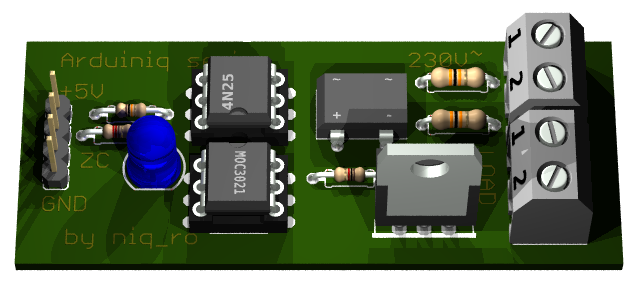
   For a good AC light dimmer, we need a zero cross detector and optocoupler who control a triac, like in this schematic (redesigned by me in Eagle PCB software after technical informations from https://arduinodiy.wordpress.com/2012/10/19/dimmer-arduino/):


   My handmade module is:

   In my case, I have 16 steps of intensity of bulb:
- bulb is off (0%):
- 1st step (6%):
- 2nd step (13%):
- 3rd step (19%):
- step no.4 (25%):
- stept no.5 (31%):
- step no. 6 (38%):
- step no.7 (44%):
- step no.8 (50%):
- step no.9 (57%):
- step no.10 (63%):
- step no.11 (69%):
- step no.12 (75%):
- step no.13 (82%):
- step no.14 (88%):
- step no.15 (94%):
- last step (100%), bulb is at maximum:
   My sketch is:
/*
AC Light Control
 Updated by Robert Twomey <rtwomey@u.washington.edu>
 Thanks to http://www.andrewkilpatrick.org/blog/?page_id=445 
 and http://www.hoelscher-hi.de/hendrik/english/dimmer.htm
 adapted sketch by niq_ro from
 http://www.tehnic.go.ro 
 http://www.niqro.3x.ro 
 http://nicuflorica.blogspot.com &  http://arduinotehniq.blogspot.com 
*/

#include <LiquidCrystal.h>
// use LiquidCrystal.h library for alphanumerical display 1602
LiquidCrystal lcd(13,12,11,10,9,8);
/*                                     -------------------
                                       |  LCD  | Arduino |
                                       -------------------
 LCD RS pin to digital pin 13          |  RS   |   D13   |
 LCD Enable pin to digital pin 12      |  E    |   D12   |
 LCD D4 pin to digital pin 11          |  D4   |   D11   |
 LCD D5 pin to digital pin 10          |  D5   |   D10   |
 LCD D6 pin to digital pin 9           |  D6   |    D9   |
 LCD D7 pin to digital pin 8           |  D7   |    D8   |
 LCD R/W pin to ground                 |  R/W  |   GND   |
                                       -------------------
*/
#include <TimerOne.h>           // Avaiable from http://www.arduino.cc/playground/Code/Timer1

volatile int i=0;               // Variable to use as a counter
volatile boolean zero_cross=0;  // Boolean to store a "switch" to tell us if we have crossed zero
int AC_pin = 3;                 // Output to Opto Triac
int buton1 = 4;                 // first button at pin 4
int buton2 = 5;                 // second button at pin 5
int dim2 = 0;                   // led control
int dim = 128;                  // Dimming level (0-128)  0 = on, 128 = 0ff
int pas = 8;                    // step for count;
// version: 4m7 (15.04.2013 - Craiova, Romania) - 16 steps, 4 button & LED blue to red (off to MAX) 
// version: 7m3 (22.01.2014 - Craiova, Romania) - 16 steps, 2 button & LCD1602

int freqStep = 75;    // This is the delay-per-brightness step in microseconds for 50Hz (change the value in 65 for 60Hz)

 
void setup() {  // Begin setup
  Serial.begin(9600);   
  pinMode(buton1, INPUT);  // set buton1 pin as input
  pinMode(buton2, INPUT);  // set buton1 pin as input
  pinMode(AC_pin, OUTPUT);                          // Set the Triac pin as output
  attachInterrupt(0, zero_cross_detect, RISING);    // Attach an Interupt to Pin 2 (interupt 0) for Zero Cross Detection
  Timer1.initialize(freqStep);                      // Initialize TimerOne library for the freq we need
  Timer1.attachInterrupt(dim_check, freqStep);      
  // Use the TimerOne Library to attach an interrupt

 lcd.begin(16, 2); // set up the LCD's number of columns and rows: 
 lcd.clear(); // clear the screen
 lcd.setCursor(2, 0); // put cursor at colon 0 and row 0
 lcd.print("16 steps AC"); // print a text
 lcd.setCursor(0, 1); // put cursor at colon 0 and row 1
 lcd.print("dimmer for bulb"); // print a text
 delay (3000);
 lcd.clear(); // clear the screen
 lcd.setCursor(1, 0); // put cursor at colon 0 and row 0
 lcd.print("this sketch is"); // print a text
 lcd.setCursor(1, 1); // put cursor at colon 0 and row 1
 lcd.print("made by niq_ro"); // print a text
 delay (3000);
 lcd.clear(); // clear the screen
}

void zero_cross_detect() {    
  zero_cross = true;               // set the boolean to true to tell our dimming function that a zero cross has occured
  i=0;
  digitalWrite(AC_pin, LOW);
}                                 

// Turn on the TRIAC at the appropriate time
void dim_check() {                   
  if(zero_cross == true) {              
    if(i>=dim) {                     
      digitalWrite(AC_pin, HIGH);  // turn on light       
      i=0;  // reset time step counter                         
      zero_cross=false;    // reset zero cross detection
    } 
    else {
      i++;  // increment time step counter                     
    }                                
  }    
}                                      

void loop() {  
  digitalWrite(buton1, HIGH);
  digitalWrite(buton2, HIGH);
  
 if (digitalRead(buton1) == LOW)   
   {
  if (dim<127)  
  {
    dim = dim + pas;
    if (dim>127) 
    {
      dim=128;
    }
  }
   }
  if (digitalRead(buton2) == LOW)   
   {
  if (dim>5)  
  {
     dim = dim - pas;
  if (dim<0) 
    {
      dim=0;
    }
   }
   }
    while (digitalRead(buton1) == LOW) {  }              
    delay(10); // waiting little bit...  
    while (digitalRead(buton2) == LOW) {  }              
    delay(10); // waiting little bit...    
           

  dim2 = 255-2*dim;
  if (dim2<0)
  {
    dim2 = 0;
  }

  Serial.print("dim=");
  Serial.print(dim);

  Serial.print("     dim2=");
  Serial.print(dim2);
  Serial.print("     dim1=");
  Serial.print(2*dim);
  Serial.print('\n');
  delay (100);
 lcd.setCursor(2, 0); // put cursor at colon 0 and row 0
 lcd.print("power is "); // print a text
 lcd.print(100-100*(255-dim2)/255);
 lcd.print("%    "); // print a text
 lcd.setCursor(1, 1); // put cursor at colon 0 and row 1
 lcd.print("dim. level="); // print a text
 lcd.print(dim);
 lcd.print("  "); // print a text
}
NOTE: For 60Hz must change
int freqStep = 75;
in 
int freqStep = 65;
!
   I made 2 movies with this AC light dimmer:
ac light dimmer with Arduino (XVII)


21.05.2019
   You can made PCB using lay file from http://arduinolab.pw and you can download Sprint Layout Viewer for open this file...


Monday, September 29, 2014

Weather station & manual adjust for RTC clock with Arduino and alphanumeric LCD1602 display

   A simple weather station give us temperature & humidity + time.
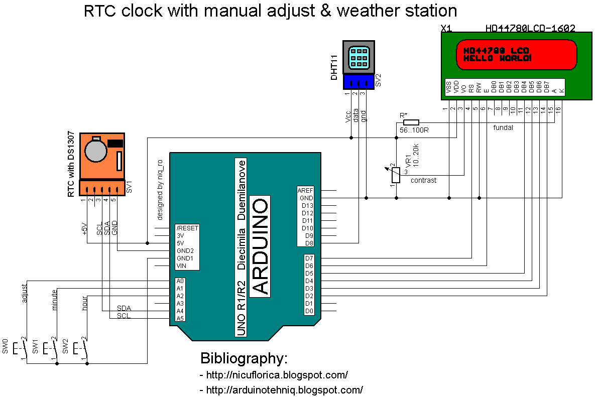
   I use a Arduino Uno board as "brain", a DHT11 sensor for humidity and temperature & RTC module with DS1307 for time and values are put on a alphanumeric LCD1602 display.
   My last schematic is:
   Practically, my montage is:
   I use this sketch:
// Date and time functions using a DS1307 RTC 
// original sketck from http://learn.adafruit.com/ds1307-real-time-clock-breakout-board-kit/
// add part with SQW=1Hz from http://tronixstuff.wordpress.com/ & http://www.bristolwatch.com/arduino/arduino_ds1307.htm
// adapted sketch by niq_ro from http://nicuflorica.blogspot.ro/
// original article from http://nicuflorica.blogspot.ro/2013/06/ceas-de-timp-real-rtc-cu-ds1307-si.html

#include <Wire.h>
#include "RTClib.h"

// include the library code:
#include <LiquidCrystal.h>
// initialize the library with the numbers of the interface pins
LiquidCrystal lcd(7, 6, 5, 4, 3, 2);

/*                                    -------------------
                                      |  LCD  | Arduino |
                                      -------------------
 LCD RS pin to digital pin 7          |  RS   |   D7    |
 LCD Enable pin to digital pin 6      |  E    |   D6    |
 LCD D4 pin to digital pin 5          |  D4   |   D6    |
 LCD D5 pin to digital pin 4          |  D5   |   D4    |
 LCD D6 pin to digital pin 3          |  D6   |   D3    |
 LCD D7 pin to digital pin 2          |  D7   |   D2    |
 LCD R/W pin to ground                |  R/W  |   GND   |
                                      -------------------
*/

RTC_DS1307 RTC;

#include <DHT.h>
#define DHTPIN 8     // what pin we're connected DHT11
#define DHTTYPE DHT11   // DHT 11 
DHT dht(DHTPIN, DHTTYPE);

byte SW0 = A0;
byte SW1 = A1;
byte SW2 = A2;

// use for hexa in zecimal conversion
int zh, uh, ore;
int zm, um, miniti;


void setup () {
  // DHT init
  dht.begin();
  // set up the LCD's number of columns and rows: 
  lcd.begin(16, 2);
  // Print a logo message to the LCD.
  lcd.print("www.tehnic.go.ro");  
  lcd.setCursor(0, 1);
  lcd.print("creat de niq_ro");
  delay (2500);
  lcd.clear();
    
   // Serial.begin(9600);
    Wire.begin();
  
// part code from http://tronixstuff.wordpress.com/
Wire.beginTransmission(0x68);
Wire.write(0x07); // move pointer to SQW address
Wire.write(0x10); // sends 0x10 (hex) 00010000 (binary) to control register - turns on square wave
Wire.endTransmission();
// end part code from http://tronixstuff.wordpress.com/

    RTC.begin();
  if (! RTC.isrunning()) {
    //Serial.println("RTC is NOT running!");
    // following line sets the RTC to the date & time this sketch was compiled
    RTC.adjust(DateTime(__DATE__, __TIME__));
  }

 pinMode(SW0, INPUT);  // for this use a slide switch
  pinMode(SW1, INPUT);  // N.O. push button switch
  pinMode(SW2, INPUT);  // N.O. push button switch

  digitalWrite(SW0, HIGH); // pull-ups on
  digitalWrite(SW1, HIGH);
  digitalWrite(SW2, HIGH);

}

void loop () {
   DateTime now = RTC.now();
  int h = dht.readHumidity();
  int t = dht.readTemperature();

   lcd.setCursor(4, 0);
   if ( now.hour() < 10)
   {
     lcd.print(" "); 
     lcd.print(now.hour(), DEC);
   }
   else
   {
   lcd.print(now.hour(), DEC);
   }
   lcd.print(":");
   if ( now.minute() < 10)
   {
     lcd.print("0"); 
     lcd.print(now.minute(), DEC);
   }
   else
   {
   lcd.print(now.minute(), DEC);
   }
   lcd.print(":");
   if ( now.second() < 10)
   {
     lcd.print("0"); 
     lcd.print(now.second(), DEC);
   }
   else
   {
   lcd.print(now.second(), DEC);
   }
     lcd.print(" "); 
 
  lcd.setCursor(1, 1);
  // lcd.print("t=");
    if ( t < 10)
   {
     lcd.print(" "); 
     lcd.print(t);
   }
   else
   {
   lcd.print(t);
   }
   //lcd.print(",0");
   lcd.write(0b11011111);
   lcd.print("C");
    
/*   lcd.setCursor(0, 1);
    if ( now.day() < 10)
   {
     lcd.print("0"); 
     lcd.print(now.day(), DEC);
   }
   else
   {
   lcd.print(now.day(), DEC);
   }
   lcd.print("/");
   if ( now.month() < 10)
   {
     lcd.print("0"); 
     lcd.print(now.month(), DEC);
   }
   else
   {
   lcd.print(now.month(), DEC);
   }
   lcd.print("/");
   lcd.print(now.year(), DEC);
   lcd.print(" "); 
*/  
   lcd.setCursor(10, 1);
  // lcd.print("H=");
   lcd.print(h);
   lcd.print("%RH");
 
   if (!(digitalRead(SW0))) set_time(); // hold the switch to set time

 
   delay(500);
}

void set_time()   {
  byte minutes1 = 0;
  byte hours1 = 0;
  byte minutes = 0;
  byte hours = 0;

  while (!digitalRead(SW0))  // set time switch must be released to exit
  {
    minutes1=minutes;
    hours1=hours;
    
     
    while (!digitalRead(SW1)) // set minutes
    { 
     minutes++;  
   // converting hexa in zecimal:
    zh = hours / 16;
    uh = hours - 16 * zh ;
    ore = 10 * zh + uh; 
    zm = minutes / 16;
    um = minutes - 16 * zm ;
    miniti = 10 * zm + um; 
  
  /*  
     for(int i = 20 ; i >0  ; i--) {
     displayNumber01(ore*100+miniti); 
     }
   */
   lcd.setCursor(4, 0);
   if ( ore < 10)
   {
     lcd.print(" "); 
     lcd.print(ore);
   }
   else
   {
   lcd.print(ore);
   }
   lcd.print(":");
   if ( miniti < 10)
   {
     lcd.print("0"); 
     lcd.print(miniti);
   }
   else
   {
   lcd.print(miniti);
   }
   lcd.print(":");
   lcd.print("00"); 
      
      if ((minutes & 0x0f) > 9) minutes = minutes + 6;
      if (minutes > 0x59) minutes = 0;
      Serial.print("Minutes = ");
      if (minutes >= 9) Serial.print("0");
      Serial.println(minutes, HEX);
    delay(150);    
    }

    while (!digitalRead(SW2)) // set hours
    { 
     hours++;          
     
   // converting hexa in zecimal:
    zh = hours / 16;
    uh = hours - 16 * zh ;
    ore = 10 * zh + uh; 
    zm = minutes / 16;
    um = minutes - 16 * zm ;
    miniti = 10 * zm + um; 
    
   /*
     for(int i = 20 ; i >0  ; i--) {
     displayNumber01(ore*100+miniti); 
     }
   */
   lcd.setCursor(4, 0);
   if ( ore < 10)
   {
     lcd.print(" "); 
     lcd.print(ore);
   }
   else
   {
   lcd.print(ore);
   }
   lcd.print(":");
   if ( miniti < 10)
   {
     lcd.print("0"); 
     lcd.print(miniti);
   }
   else
   {
   lcd.print(miniti);
   }
   lcd.print(":");
   lcd.print("00");
      
      if ((hours & 0x0f) > 9) hours =  hours + 6;
      if (hours > 0x23) hours = 0;
      Serial.print("Hours = ");
      if (hours <= 9) Serial.print("0");
      Serial.println(hours, HEX);
    delay(150);
    }

    Wire.beginTransmission(0x68); // activate DS1307
    Wire.write(0); // where to begin
    Wire.write(0x00);          //seconds
    Wire.write(minutes);          //minutes
    Wire.write(0x80 | hours);    //hours (24hr time)
    Wire.write(0x06);  // Day 01-07
    Wire.write(0x01);  // Date 0-31
    Wire.write(0x05);  // month 0-12
    Wire.write(0x09);  // Year 00-99
    Wire.write(0x10); // Control 0x10 produces a 1 HZ square wave on pin 7. 
    Wire.endTransmission();
  
    // converting hexa in zecimal:
    zh = hours / 16;
    uh = hours - 16 * zh ;
    ore = 10 * zh + uh; 
    zm = minutes / 16;
    um = minutes - 16 * zm ;
    miniti = 10 * zm + um; 
    
   /*  for(int i = 20 ; i >0  ; i--) {
     displayNumber01(ore*100+miniti); 
     }
 //  delay(150);
    */

   lcd.setCursor(4, 0);
   if ( ore < 10)
   {
     lcd.print(" "); 
     lcd.print(ore);
   }
   else
   {
   lcd.print(ore);
   }
   lcd.print(":");
   if ( miniti < 10)
   {
     lcd.print("0"); 
     lcd.print(miniti);
   }
   else
   {
   lcd.print(miniti);
   }
   lcd.print(":");
   lcd.print("00");
}
   I made a movie with some usefull comments, named weather & manual adjust for RTC clock with Arduino and LCD1602 display:
   Like in previous article, if you want to change time, must push and hold SW0 (adjust) switch and display is change on 0:00, then push SW2 (hour) or SW1 (minute) repeatedly until time is ok, after this realise SW0, and time is put in RTC.