Total Pageviews

Showing posts with label Arduino. Show all posts

Saturday, October 18, 2014

BMP180 sensor and Arduino

   BMP180 sensor can give us information about pressure an temperature.
   This sensor is delivered on small module with 4 pins: Vin (+3.3V), GND, SDA and SCL.
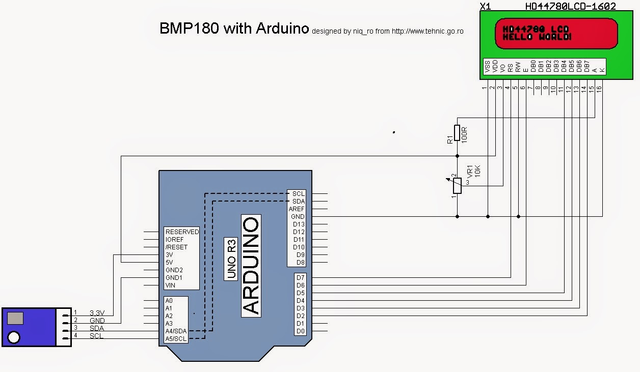
   For testing, schematic is very simple:
   For control BMP180 sensor I use Adafruit-BMP085-Library, them test the example sketch.
   For a stand alone weather station with information about temperature and presure, I put a alphanumeric LCD display with 16 colons and 2 rows (1602):
and test montage is:
   I use this sketch:
// adapted sketch by niq_ro from http://nicuflorica.blogspot.ro/ & http://arduinotehniq.blogspot.com/
// https://github.com/adafruit/Adafruit-BMP085-Library
#include <Wire.h>
#include <Adafruit_BMP085.h>

/*************************************************** 
  This is an example for the BMP085 Barometric Pressure & Temp Sensor
  Designed specifically to work with the Adafruit BMP085 Breakout 
  ----> https://www.adafruit.com/products/391
  These displays use I2C to communicate, 2 pins are required to  
  interface
  Adafruit invests time and resources providing this open source code, 
  please support Adafruit and open-source hardware by purchasing 
  products from Adafruit!

  Written by Limor Fried/Ladyada for Adafruit Industries.  
  BSD license, all text above must be included in any redistribution
 ****************************************************/

// Connect VCC of the BMP085 sensor to 3.3V (NOT 5.0V!)
// Connect GND to Ground
// Connect SCL to i2c clock - on '168/'328 Arduino Uno/Duemilanove/etc thats Analog 5
// Connect SDA to i2c data - on '168/'328 Arduino Uno/Duemilanove/etc thats Analog 4
// EOC is not used, it signifies an end of conversion
// XCLR is a reset pin, also not used here

// include the library code:
#include <LiquidCrystal.h>
// initialize the library with the numbers of the interface pins
LiquidCrystal lcd(7, 6, 5, 4, 3, 2);

/*                                    -------------------
                                      |  LCD  | Arduino |
                                      -------------------
 LCD RS pin to digital pin 7          |  RS   |   D7    |
 LCD Enable pin to digital pin 6      |  E    |   D6    |
 LCD D4 pin to digital pin 5          |  D4   |   D6    |
 LCD D5 pin to digital pin 4          |  D5   |   D4    |
 LCD D6 pin to digital pin 3          |  D6   |   D3    |
 LCD D7 pin to digital pin 2          |  D7   |   D2    |
 LCD R/W pin to ground                |  R/W  |   GND   |
                                      -------------------
*/


Adafruit_BMP085 bmp;
  
void setup() {
  lcd.begin(16, 2);
  // Print a logo message to the LCD.
  lcd.print("www.tehnic.go.ro");  
  lcd.setCursor(0, 1);
  lcd.print("creat de niq_ro");
  delay (2500);
  lcd.clear();

  // Print another message to the LCD.
  lcd.setCursor(2, 0);
  lcd.print("termometru -");  
  lcd.setCursor(0, 1);
  lcd.print("barometru ver1.0");
  delay (2500);
  lcd.clear();

  Serial.begin(9600);
  if (!bmp.begin()) {
 Serial.println("nu exita senzor compatibil BMP085 sau BMP180");
 while (1) {}
  }
}
  
void loop() {
    Serial.print("Temperatura = ");
    Serial.print(bmp.readTemperature());
    Serial.println(" *C");
    
    Serial.print("Presiune = ");
    Serial.print(bmp.readPressure());
    Serial.print(" Pa / ");
    
 //   Serial.print("Presiune = ");
    float presiune1 = bmp.readPressure()/101.325;
    presiune1 = presiune1 * 0.760;
    Serial.print(presiune1);
    Serial.println(" mmHg");
    
    
    // Calculate altitude assuming 'standard' barometric
    // pressure of 1013.25 millibar = 101325 Pascal
    Serial.print("Altitudine = ");
    Serial.print(bmp.readAltitude());
    Serial.println(" m");

    Serial.print("Presiune la nivelul marii (calculata) = ");
    Serial.print(bmp.readSealevelPressure());
    Serial.print(" Pa / ");
    
    // http://en.wikipedia.org/wiki/Atmospheric_pressure#Mean_sea_level_pressure
  //  Serial.print("Presiure la nivelul marii (calculata) = ");
    float presiune = bmp.readSealevelPressure()/101.325;
    presiune = presiune * 0.760;
    Serial.print(presiune);
    Serial.println(" mmHg");
    

  // you can get a more precise measurement of altitude
  // if you know the current sea level pressure which will
  // vary with weather and such. If it is 1015 millibars
  // that is equal to 101500 Pascals.
    Serial.print("Altitudine reala = ");
    Serial.print(bmp.readAltitude(101500));
    Serial.println(" m");
    
    Serial.println();
    
    
   lcd.setCursor(1, 0);
   lcd.print("temp.=  ");
    if ( bmp.readTemperature() < 10)
   {
     lcd.print(" "); 
     lcd.print(bmp.readTemperature());
   }
   else
   {
   lcd.print(bmp.readTemperature(),1);
   }
   lcd.write(0b11011111);
   lcd.print("C   ");
   
   lcd.setCursor(1, 1);
   lcd.print("pres.= p");
   lcd.print(presiune,0);
   lcd.print("mmHg  ");
    
   delay(2500);
}
24.11.2014
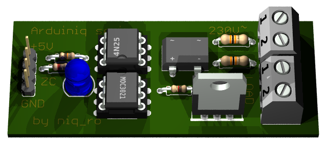
   In last weak-end, I received 3 pics from Dave (http://g4rvh.wordpress.com/) with a shield for Arduino Uno, made after my schematic:
   He made with board with CNC Cutter:
   I change the sketch for present the temperature in Fahrenheit, not in Celsius degree, using information from article http://www.mathsisfun.com/temperature-conversion.html:

Wednesday, October 1, 2014

AC light dimmer with Arduino

   A very interesting device is a AC light dimmer. With Arduino, we can made control with potentiometer (like in shops) or with push buttons. 
   I try more version, and now I present you a AC light dimmer with 2 push buttons for 16 steps and a alphanumerical LCD1602 display. I use 100W incandescent bulb at 230V/50Hz.
   My schematic is:
   For a good AC light dimmer, we need a zero cross detector and optocoupler who control a triac, like in this schematic (redesigned by me in Eagle PCB software after technical informations from https://arduinodiy.wordpress.com/2012/10/19/dimmer-arduino/):


   My handmade module is:

   In my case, I have 16 steps of intensity of bulb:
- bulb is off (0%):
- 1st step (6%):
- 2nd step (13%):
- 3rd step (19%):
- step no.4 (25%):
- stept no.5 (31%):
- step no. 6 (38%):
- step no.7 (44%):
- step no.8 (50%):
- step no.9 (57%):
- step no.10 (63%):
- step no.11 (69%):
- step no.12 (75%):
- step no.13 (82%):
- step no.14 (88%):
- step no.15 (94%):
- last step (100%), bulb is at maximum:
   My sketch is:
/*
AC Light Control
 Updated by Robert Twomey <rtwomey@u.washington.edu>
 Thanks to http://www.andrewkilpatrick.org/blog/?page_id=445 
 and http://www.hoelscher-hi.de/hendrik/english/dimmer.htm
 adapted sketch by niq_ro from
 http://www.tehnic.go.ro 
 http://www.niqro.3x.ro 
 http://nicuflorica.blogspot.com &  http://arduinotehniq.blogspot.com 
*/

#include <LiquidCrystal.h>
// use LiquidCrystal.h library for alphanumerical display 1602
LiquidCrystal lcd(13,12,11,10,9,8);
/*                                     -------------------
                                       |  LCD  | Arduino |
                                       -------------------
 LCD RS pin to digital pin 13          |  RS   |   D13   |
 LCD Enable pin to digital pin 12      |  E    |   D12   |
 LCD D4 pin to digital pin 11          |  D4   |   D11   |
 LCD D5 pin to digital pin 10          |  D5   |   D10   |
 LCD D6 pin to digital pin 9           |  D6   |    D9   |
 LCD D7 pin to digital pin 8           |  D7   |    D8   |
 LCD R/W pin to ground                 |  R/W  |   GND   |
                                       -------------------
*/
#include <TimerOne.h>           // Avaiable from http://www.arduino.cc/playground/Code/Timer1

volatile int i=0;               // Variable to use as a counter
volatile boolean zero_cross=0;  // Boolean to store a "switch" to tell us if we have crossed zero
int AC_pin = 3;                 // Output to Opto Triac
int buton1 = 4;                 // first button at pin 4
int buton2 = 5;                 // second button at pin 5
int dim2 = 0;                   // led control
int dim = 128;                  // Dimming level (0-128)  0 = on, 128 = 0ff
int pas = 8;                    // step for count;
// version: 4m7 (15.04.2013 - Craiova, Romania) - 16 steps, 4 button & LED blue to red (off to MAX) 
// version: 7m3 (22.01.2014 - Craiova, Romania) - 16 steps, 2 button & LCD1602

int freqStep = 75;    // This is the delay-per-brightness step in microseconds for 50Hz (change the value in 65 for 60Hz)

 
void setup() {  // Begin setup
  Serial.begin(9600);   
  pinMode(buton1, INPUT);  // set buton1 pin as input
  pinMode(buton2, INPUT);  // set buton1 pin as input
  pinMode(AC_pin, OUTPUT);                          // Set the Triac pin as output
  attachInterrupt(0, zero_cross_detect, RISING);    // Attach an Interupt to Pin 2 (interupt 0) for Zero Cross Detection
  Timer1.initialize(freqStep);                      // Initialize TimerOne library for the freq we need
  Timer1.attachInterrupt(dim_check, freqStep);      
  // Use the TimerOne Library to attach an interrupt

 lcd.begin(16, 2); // set up the LCD's number of columns and rows: 
 lcd.clear(); // clear the screen
 lcd.setCursor(2, 0); // put cursor at colon 0 and row 0
 lcd.print("16 steps AC"); // print a text
 lcd.setCursor(0, 1); // put cursor at colon 0 and row 1
 lcd.print("dimmer for bulb"); // print a text
 delay (3000);
 lcd.clear(); // clear the screen
 lcd.setCursor(1, 0); // put cursor at colon 0 and row 0
 lcd.print("this sketch is"); // print a text
 lcd.setCursor(1, 1); // put cursor at colon 0 and row 1
 lcd.print("made by niq_ro"); // print a text
 delay (3000);
 lcd.clear(); // clear the screen
}

void zero_cross_detect() {    
  zero_cross = true;               // set the boolean to true to tell our dimming function that a zero cross has occured
  i=0;
  digitalWrite(AC_pin, LOW);
}                                 

// Turn on the TRIAC at the appropriate time
void dim_check() {                   
  if(zero_cross == true) {              
    if(i>=dim) {                     
      digitalWrite(AC_pin, HIGH);  // turn on light       
      i=0;  // reset time step counter                         
      zero_cross=false;    // reset zero cross detection
    } 
    else {
      i++;  // increment time step counter                     
    }                                
  }    
}                                      

void loop() {  
  digitalWrite(buton1, HIGH);
  digitalWrite(buton2, HIGH);
  
 if (digitalRead(buton1) == LOW)   
   {
  if (dim<127)  
  {
    dim = dim + pas;
    if (dim>127) 
    {
      dim=128;
    }
  }
   }
  if (digitalRead(buton2) == LOW)   
   {
  if (dim>5)  
  {
     dim = dim - pas;
  if (dim<0) 
    {
      dim=0;
    }
   }
   }
    while (digitalRead(buton1) == LOW) {  }              
    delay(10); // waiting little bit...  
    while (digitalRead(buton2) == LOW) {  }              
    delay(10); // waiting little bit...    
           

  dim2 = 255-2*dim;
  if (dim2<0)
  {
    dim2 = 0;
  }

  Serial.print("dim=");
  Serial.print(dim);

  Serial.print("     dim2=");
  Serial.print(dim2);
  Serial.print("     dim1=");
  Serial.print(2*dim);
  Serial.print('\n');
  delay (100);
 lcd.setCursor(2, 0); // put cursor at colon 0 and row 0
 lcd.print("power is "); // print a text
 lcd.print(100-100*(255-dim2)/255);
 lcd.print("%    "); // print a text
 lcd.setCursor(1, 1); // put cursor at colon 0 and row 1
 lcd.print("dim. level="); // print a text
 lcd.print(dim);
 lcd.print("  "); // print a text
}
NOTE: For 60Hz must change
int freqStep = 75;
in 
int freqStep = 65;
!
   I made 2 movies with this AC light dimmer:
ac light dimmer with Arduino (XVII)


21.05.2019
   You can made PCB using lay file from http://arduinolab.pw and you can download Sprint Layout Viewer for open this file...


Monday, September 29, 2014

Weather station & manual adjust for RTC clock with Arduino and alphanumeric LCD1602 display

   A simple weather station give us temperature & humidity + time.
   I use a Arduino Uno board as "brain", a DHT11 sensor for humidity and temperature & RTC module with DS1307 for time and values are put on a alphanumeric LCD1602 display.
   My last schematic is:
   Practically, my montage is:
   I use this sketch:
// Date and time functions using a DS1307 RTC 
// original sketck from http://learn.adafruit.com/ds1307-real-time-clock-breakout-board-kit/
// add part with SQW=1Hz from http://tronixstuff.wordpress.com/ & http://www.bristolwatch.com/arduino/arduino_ds1307.htm
// adapted sketch by niq_ro from http://nicuflorica.blogspot.ro/
// original article from http://nicuflorica.blogspot.ro/2013/06/ceas-de-timp-real-rtc-cu-ds1307-si.html

#include <Wire.h>
#include "RTClib.h"

// include the library code:
#include <LiquidCrystal.h>
// initialize the library with the numbers of the interface pins
LiquidCrystal lcd(7, 6, 5, 4, 3, 2);

/*                                    -------------------
                                      |  LCD  | Arduino |
                                      -------------------
 LCD RS pin to digital pin 7          |  RS   |   D7    |
 LCD Enable pin to digital pin 6      |  E    |   D6    |
 LCD D4 pin to digital pin 5          |  D4   |   D6    |
 LCD D5 pin to digital pin 4          |  D5   |   D4    |
 LCD D6 pin to digital pin 3          |  D6   |   D3    |
 LCD D7 pin to digital pin 2          |  D7   |   D2    |
 LCD R/W pin to ground                |  R/W  |   GND   |
                                      -------------------
*/

RTC_DS1307 RTC;

#include <DHT.h>
#define DHTPIN 8     // what pin we're connected DHT11
#define DHTTYPE DHT11   // DHT 11 
DHT dht(DHTPIN, DHTTYPE);

byte SW0 = A0;
byte SW1 = A1;
byte SW2 = A2;

// use for hexa in zecimal conversion
int zh, uh, ore;
int zm, um, miniti;


void setup () {
  // DHT init
  dht.begin();
  // set up the LCD's number of columns and rows: 
  lcd.begin(16, 2);
  // Print a logo message to the LCD.
  lcd.print("www.tehnic.go.ro");  
  lcd.setCursor(0, 1);
  lcd.print("creat de niq_ro");
  delay (2500);
  lcd.clear();
    
   // Serial.begin(9600);
    Wire.begin();
  
// part code from http://tronixstuff.wordpress.com/
Wire.beginTransmission(0x68);
Wire.write(0x07); // move pointer to SQW address
Wire.write(0x10); // sends 0x10 (hex) 00010000 (binary) to control register - turns on square wave
Wire.endTransmission();
// end part code from http://tronixstuff.wordpress.com/

    RTC.begin();
  if (! RTC.isrunning()) {
    //Serial.println("RTC is NOT running!");
    // following line sets the RTC to the date & time this sketch was compiled
    RTC.adjust(DateTime(__DATE__, __TIME__));
  }

 pinMode(SW0, INPUT);  // for this use a slide switch
  pinMode(SW1, INPUT);  // N.O. push button switch
  pinMode(SW2, INPUT);  // N.O. push button switch

  digitalWrite(SW0, HIGH); // pull-ups on
  digitalWrite(SW1, HIGH);
  digitalWrite(SW2, HIGH);

}

void loop () {
   DateTime now = RTC.now();
  int h = dht.readHumidity();
  int t = dht.readTemperature();

   lcd.setCursor(4, 0);
   if ( now.hour() < 10)
   {
     lcd.print(" "); 
     lcd.print(now.hour(), DEC);
   }
   else
   {
   lcd.print(now.hour(), DEC);
   }
   lcd.print(":");
   if ( now.minute() < 10)
   {
     lcd.print("0"); 
     lcd.print(now.minute(), DEC);
   }
   else
   {
   lcd.print(now.minute(), DEC);
   }
   lcd.print(":");
   if ( now.second() < 10)
   {
     lcd.print("0"); 
     lcd.print(now.second(), DEC);
   }
   else
   {
   lcd.print(now.second(), DEC);
   }
     lcd.print(" "); 
 
  lcd.setCursor(1, 1);
  // lcd.print("t=");
    if ( t < 10)
   {
     lcd.print(" "); 
     lcd.print(t);
   }
   else
   {
   lcd.print(t);
   }
   //lcd.print(",0");
   lcd.write(0b11011111);
   lcd.print("C");
    
/*   lcd.setCursor(0, 1);
    if ( now.day() < 10)
   {
     lcd.print("0"); 
     lcd.print(now.day(), DEC);
   }
   else
   {
   lcd.print(now.day(), DEC);
   }
   lcd.print("/");
   if ( now.month() < 10)
   {
     lcd.print("0"); 
     lcd.print(now.month(), DEC);
   }
   else
   {
   lcd.print(now.month(), DEC);
   }
   lcd.print("/");
   lcd.print(now.year(), DEC);
   lcd.print(" "); 
*/  
   lcd.setCursor(10, 1);
  // lcd.print("H=");
   lcd.print(h);
   lcd.print("%RH");
 
   if (!(digitalRead(SW0))) set_time(); // hold the switch to set time

 
   delay(500);
}

void set_time()   {
  byte minutes1 = 0;
  byte hours1 = 0;
  byte minutes = 0;
  byte hours = 0;

  while (!digitalRead(SW0))  // set time switch must be released to exit
  {
    minutes1=minutes;
    hours1=hours;
    
     
    while (!digitalRead(SW1)) // set minutes
    { 
     minutes++;  
   // converting hexa in zecimal:
    zh = hours / 16;
    uh = hours - 16 * zh ;
    ore = 10 * zh + uh; 
    zm = minutes / 16;
    um = minutes - 16 * zm ;
    miniti = 10 * zm + um; 
  
  /*  
     for(int i = 20 ; i >0  ; i--) {
     displayNumber01(ore*100+miniti); 
     }
   */
   lcd.setCursor(4, 0);
   if ( ore < 10)
   {
     lcd.print(" "); 
     lcd.print(ore);
   }
   else
   {
   lcd.print(ore);
   }
   lcd.print(":");
   if ( miniti < 10)
   {
     lcd.print("0"); 
     lcd.print(miniti);
   }
   else
   {
   lcd.print(miniti);
   }
   lcd.print(":");
   lcd.print("00"); 
      
      if ((minutes & 0x0f) > 9) minutes = minutes + 6;
      if (minutes > 0x59) minutes = 0;
      Serial.print("Minutes = ");
      if (minutes >= 9) Serial.print("0");
      Serial.println(minutes, HEX);
    delay(150);    
    }

    while (!digitalRead(SW2)) // set hours
    { 
     hours++;          
     
   // converting hexa in zecimal:
    zh = hours / 16;
    uh = hours - 16 * zh ;
    ore = 10 * zh + uh; 
    zm = minutes / 16;
    um = minutes - 16 * zm ;
    miniti = 10 * zm + um; 
    
   /*
     for(int i = 20 ; i >0  ; i--) {
     displayNumber01(ore*100+miniti); 
     }
   */
   lcd.setCursor(4, 0);
   if ( ore < 10)
   {
     lcd.print(" "); 
     lcd.print(ore);
   }
   else
   {
   lcd.print(ore);
   }
   lcd.print(":");
   if ( miniti < 10)
   {
     lcd.print("0"); 
     lcd.print(miniti);
   }
   else
   {
   lcd.print(miniti);
   }
   lcd.print(":");
   lcd.print("00");
      
      if ((hours & 0x0f) > 9) hours =  hours + 6;
      if (hours > 0x23) hours = 0;
      Serial.print("Hours = ");
      if (hours <= 9) Serial.print("0");
      Serial.println(hours, HEX);
    delay(150);
    }

    Wire.beginTransmission(0x68); // activate DS1307
    Wire.write(0); // where to begin
    Wire.write(0x00);          //seconds
    Wire.write(minutes);          //minutes
    Wire.write(0x80 | hours);    //hours (24hr time)
    Wire.write(0x06);  // Day 01-07
    Wire.write(0x01);  // Date 0-31
    Wire.write(0x05);  // month 0-12
    Wire.write(0x09);  // Year 00-99
    Wire.write(0x10); // Control 0x10 produces a 1 HZ square wave on pin 7. 
    Wire.endTransmission();
  
    // converting hexa in zecimal:
    zh = hours / 16;
    uh = hours - 16 * zh ;
    ore = 10 * zh + uh; 
    zm = minutes / 16;
    um = minutes - 16 * zm ;
    miniti = 10 * zm + um; 
    
   /*  for(int i = 20 ; i >0  ; i--) {
     displayNumber01(ore*100+miniti); 
     }
 //  delay(150);
    */

   lcd.setCursor(4, 0);
   if ( ore < 10)
   {
     lcd.print(" "); 
     lcd.print(ore);
   }
   else
   {
   lcd.print(ore);
   }
   lcd.print(":");
   if ( miniti < 10)
   {
     lcd.print("0"); 
     lcd.print(miniti);
   }
   else
   {
   lcd.print(miniti);
   }
   lcd.print(":");
   lcd.print("00");
}
   I made a movie with some usefull comments, named weather & manual adjust for RTC clock with Arduino and LCD1602 display:
   Like in previous article, if you want to change time, must push and hold SW0 (adjust) switch and display is change on 0:00, then push SW2 (hour) or SW1 (minute) repeatedly until time is ok, after this realise SW0, and time is put in RTC.