Total Pageviews

Monday, July 6, 2015

KTM-S1201: 12 Digit 7-segment LCD display

original article !!

   Like SDA5708: 8 character 7x5 dot matrix LED display, this display is received as gift for test.
   KTM-S1201 display is drived by NEC D7225 (UPD7225G) chip and I found a very usefull article named Arduino and KTM-S1201 LCD modules
   I use also info from www.pongrance.com
   For control this display with Arduino sketch must download KTMS1201.h file and put in same directory with sketch:
and in Arduino IDE software you see:
   First step was to made a pcb for schematic with a 10..20k variable resistor for contrast:
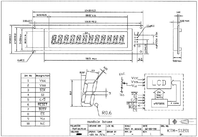
   Schematic is made after nest info:
   Test schematic is:
   After upload the example sketches and few changes in sketches, on display I can see:
   After that, I made a new schematic with DHT22 (AM2302) sensor:
   I write a sketch named KTMS1201_DHT22.ino and on display I can see:
   I finished the schematic with RTC clock module (made with DS3231, but work fine with DS1307) and KY-040 rotary encoder:
After upload KTMS1201_DHT22_RTC_ver1m0.ino sketch, I cand see:
- hour:
- humidity and temperature:
- data, after a short push:
- change mode, first year, after a long push (3-4 seconds):
- change month:
- change day:
- change hours:
- change minutes:
   I made few movie:
    Final sketch is KTMS1201_DHT22_RTC_ver1m1.ino and I use a changed KTMS1201.h file for C and Y letters:
   Finally, I change the sketch (see KTMS1201_DHT22_RTC_ver1m1b.ino) for another style for humidity:

Friday, July 3, 2015

SDA5708: 8 character 7x5 dot matrix LED display

original article !

   Recently, I received as gift, for tests, a special display named SDA5708. This display was used in old sat receiver Nokia DBOX1 and is,like in title, with 8 character made, each, with 7x5 dot display led.
   After I received this display, I search technical info about this display and I found some:
http://www.bralug.de/wiki/Display_SDA5708
http://www.sbprojects.com/knowledge/footprints/sda5708/index.php
http://blog.smue.org/archives/433-DBOX1-SDA5708-display-+-arduino.html 
   Using info from second article, I redesigned connection schematic:
   I made a schematic using info from 3rd article:
and after I upload the changed example sketch, on display I can see:
I made few changes in example sketch, for display my ID used on net:
   After this first step, I put an AM2302 with 4k7 rezistor (same as DHT22 sensor) for read temperature and humidity info:
and I change the sketch for see:
   Result are good and I put an RTC clock module made with DS3231 and momentary switch like in schematic:

and I can see, after I write sketch named SDA5708_DHT22_ceas_simplu.ino:
   Now, I can go to nest level, a full weather station with adjusting clock usin rotary encoder.
   I made this schematic:
   After I write a full sketch named SDA5708_DHT22_ceas_encoder_v1m2.ino, cyclic, on display I can see:
- clock:
- temerature and relative humidity:
   After a short push, I can see the data (day.mounth.year):
   After a long push (3-4 seconds), I can d change the data:
- year:
- month:
- day:
- hour:
- minutes:
   I made a movie, named weather station with adjusting clock on SDA5708 display where you can see more than I write:


Wednesday, May 20, 2015

Arduino thermostat with 2 thresholds on 4 digit 7-segment display

   This thermostat with few components has same schematic with previous thermostat:
 
   Few pics with Arduino Mega board (must just few changes in sketch for works with Uno or Mega):
- desired temperature is ok:
- actual temperature is less than desired temperature:
- actual temperature is much than desired temperature:
   After push the MENU button, low threshold can be set:
and if I push the "-" button value is decrease with 1 degree Celsius at every push and if I push the "+" button value is increase with 1 degree Celsius at every push.
   If I push MENU button, high threshold can be set:
and if I push the "-" button value is decrease with 1 degree Celsius at every push and if I push the "+" button value is increase with 1 degree Celsius at every push. If high threshold is set less low threshold, Arduino automatically change high threshold = low threshold + 1 degree Celsius.
   Sketch for this thermostat is put at https://github.com/tehniq3/!
   For best results, I use internal reference (1.1V) and for Arduino Uno board in sketch must see:
and for Mega board must comment fisrt line and uncomment next line !!!
   Fist time when upload the sketch, must write default value for low and high thesholds:
after that must put comments and upload the sketch again:
   I made a movie with this thermostat, named Arduino thermostat with 2 thresholds

Arduino thermostat on 7-segment LED display

   I designed a thermostat with few components using an Arduino board.
   I use LM35DZ for temperture sensor, KW4-563ASA display (4 digit 7-segment with common anode), RGB led, 3 button (push button) for select and change the value for desired temperature and for hysteresis.
   I designed this schematic:
who is used also for an thermostat with 2 thesholds (must change the sketch).
   If measured temperature is less than desired temperture, blue led is on:
and if is to much, red led is on:
   If I push the MENU buton, display is change in:
(in right side, is "c" instead "C"). 
   If I push "-" button, temperature value decrease with 0.1 degree Celsius for each push, if I push "+" button, temperature increase with 0,1 degree Celsius for each push.
   After that, if I push again MENU button, I will see:
and I can change the value with 0.1 degree, like at desired temperature.
   Values for desired temperature and hysteresis are write and stored in internal EEPROM memory of microcontroler (any Arduno board has an microcontroller on it.)
   For easy understund this, I made a movie named Arduino thermostat
   Skech for this thermostat is put on https://github.com/tehniq3/thermostat !!!

PS:  Fist time when upload the sketch, must write default value for desired temprature and hysteresis:
after that, must comment the 3 lines:
   Actual sketch work with Arduino Uno board and you can see:
but for work with Arduino Mega board you must comment first line and uncomment second line:
PS2: If you want to connect a relay for control a heater system, subroutine leduri() must be changed in:
void leduri() {
 digitalWrite(CALD, LOW);
 digitalWrite(RECE, LOW);

if ( t0*10 < tset ) 
{  digitalWrite(RECE, HIGH);
   digitalWrite(CALD, LOW);
   pornire = 1;
}
if ( t0*10 > tset + dt ) 
{  digitalWrite(CALD, HIGH);
   digitalWrite(RECE, LOW);
   pornire = 0;
}

if (( t0*10 <= tset+dt ) && ( t0*10 >= tset )) {
if (pornire == 1)
{  digitalWrite(CALD, LOW);
   digitalWrite(RECE, HIGH);
}
if (pornire == 0)
{  digitalWrite(CALD, LOW);
   digitalWrite(RECE, LOW);
}
}
}
and at begin of sketch must define int pornire; and in setup must put pornire = 0; !!
   You can download changed sketch from https://github.com/tehniq3.
   In movie namend Arduino thermostat (2) you can see the changed style, like usual thermostat for a heater: