Total Pageviews

Sunday, August 26, 2018

WebServer with ESP32

   I buy an Geekcreit® ESP32-DevKit development board and I want to test quickly, so I use information from article ESP32 Web Server – Arduino IDE writted by Rui Santos.
    I discover that development boar has 2 built-in leds, one at GPIO0 and one at GPIO27 (while om net is mentioned just GPIO27), so I change the sketch to use this leds and to invert logical level because leds are connected thru resistors at +3,3V not GND.
   Changed sketch is ESP32_WebServer.ino and you can upload in ESP32 development board after follow steps from article Installing the ESP32 Board in Arduino IDE (Windows instructions).
   After upload my sketch, in serial monitor it appear IP adress for local WebServer
   First, both leds are off
but after you push virtual button from webserver named GPIO0 led will lit (upper button)
and after push botton button (GPIO27) apropriate led will lit
 To have just GPIO27 led lit, must pust on GPIO0 button
   I made Web Server with red ESP32 board from Banggood movie where is presented how WebSwever control the two leds

Friday, August 24, 2018

Show Temperature and Humidity as WiFi SSID with ESP8266 and DHT22 Sensor

   I use informations from article Show Temperature and Humidity as WiFi SSID with ESP8266 and HTU21D Sensor, just change sensor. Instead HTU21D, I use DHT22 (AM2302), my schematic is
   I program NodeMCU development board (work any development board with ESP8266: Lolin, Adafruit, WeMos, etc) with Arduino IDe software, using dht_custom_ssid_exp8266_1.ino sketch.
   For frogram ESP8266 as Arduino must follow steps from เพิ่มบอร์ด ESP8266 ใน Arduino IDE (or from my article named Placa NodeMcu v.0.9 programata in Arduino IDE).
  Also, you need 3 library:
- DHT
Pstring
Streaming
   Now, we can find Wi-Fi network with custon name (ESP8266 is in AP mode):
- on Android phone
- on PC with Windows 7
   Name of SSID will change at every 10 seconds, but best view is in Android phone (quick change).
   I made Show Temperature and Humidity as WiFi SSID with ESP8266 and DHT22 Sensor video to see how this system work:


Saturday, August 18, 2018

128x128 1.5" OLED display with SSD1327 controlled by ESP32

original article

   I received an interesting display for test (OLED technology, 128x128 resolutios, SSD1327 driver) for made to work with ESP32 development board.

   Default, connexion is for SPI, but you can change to i2c connexion, see in schematic from here.
   I search info and after few tests, I used with good results u8g2 library  and my config is
U8G2_SSD1327_MIDAS_128X128_F_4W_SW_SPI u8g2(U8G2_R0, /* clock=*/ 13, /* data=*/ 12, /* cs=*/ 14, /* dc=*/ 27, /* reset=*/ 26);
   You can see 1.5” OLED display with ESP32 movie


Tuesday, July 3, 2018

128x160 1.8" TFT display with ST7735 controlled by ESP32

   I give an 1.8" TFT display with 128x160 resolution. It use ST7735 as driver.
   I wanted to use together with an ESP32 development board and first I search information about this connexion but just two article and an topic on Arduino forum was usefull.
   First usefull article was 128×128 Colour LCD to ESP32 from www.xtronical.com. Schematic for connexion is
It used Xtronical ST7735 library derivated from Adafruit ST7735 library... I tested, but I can't display all info in all four modes (0, 90, 180 and 270 degree) even if I change resolution in library as 128x160 not 128x128.
  I made 128x160 1.8" TFT display with ST7735 controlled by ESP32 to be more clear
   In article Cheap 1.77 Inch TFT-screen on ESP32 from https://www.hackster.io/ and  an topic on Arduino forum I discover Bodmer's TFT_eSPI library. After few time testing, I can see ok info on display.
   My changed User_Setup.h works fine for me, see in 128x160 1.8" TFT display with ST7735 controlled by ESP32 (2)


Thursday, November 2, 2017

"Daytime Running Light" module (DRL) with ATtiny85

   A reader of my sites and blogs, Mr. Liviu Hinoveanu wanted to replace classical DRL module made with 555 with Attiny85 programmed in Arduino style.
   He send me the schematic and PCB designed with Livewire and PCB Wisard software:

   After I undertand what module must work, I write DRL_ATtiny85.ino sketch.
   Mr. Hinoveanu made module and upload sketch in ATiny85 like in article from Programarea unui microcontroler ATTiny85 cu sketch Arduino.
    In movie named DRL cu ATtiny85 you can see who module work, but description are in romanian language:
   After engine start, I can adjunst in few stepts intensity of lights (from minimum to maximum, by pushing button repeatedly, when value in smaximum and pres button intensity go to minimum...).
   If I set manual light from original light switch, module is off.
   Whne enggine strop, module made a "dinamic lights"style from maximum to off in short time.
   Module detect engine start by increase tension value on battery because work the alternator).


Thursday, September 28, 2017

4-digit 7-segment led display thermometer using 1N4148 diode

original version (written in Romanian)

   You can made a cheap thermometer using few components: clone Arduino board (in my case, I use Arduino Nano board with uC ATmega 168, but work with Arduino nano with ATmega328, Arduino Uno, leonardo, etc), a 1N4148 diode, 4-digit 7-segment led display with common cathode or common anode (just few changes in sketch), an breadboard and some wires.
   Schematic is very simple:
  I write first sketch named diode_thermometer_display_1.ino and on dissplay temperature is as integer:
,
but if it use diode_thermometer_display_2.ino sketch, value is with decimal value:
   I use info from article https://www.hackster.io/microst/thermometer-diode-based-524613 and I test sketch:
see 1N4148 diode as temperature sensor movie:
   For project with display, I made thermometer with 1N4148 diode as sensor on multiplexed led display
   For understand how can be use a diode as temperature sensor see figure 1 from 1N4148 diode datasheet
and article:
DIODE-BASED TEMPERATURE MEASUREMENT (Burr-Brown)
Accurate Temperature Sensing with an External P-N Junction (Linear Technology)

Monday, August 21, 2017

Revival and use the Arduino ESP8266 Wifi Shield Version 1.0 by Wang Tongze

   Some time ago (2015) I bought "Arduino ESP8266 Wifi Shield Version 1.0 by Wang Tongze" without more documentation... neither now 😕 Last year, I write an article in my language with this board, because I pressed and shuffled and firmware was erased... But let's start as normal condition...

   For normal operation mode switch must be in this position:
  In first tests, I connect Rx-Tx from this shield at Arduino Mega at Rx1-Tx1 pins, for see how work...
  I upload ESP8266_mega_serialtest.ino with 112500bps instead 9600bps (board is Arduino Mega, shield witj ESP8266 is just accessory)
   I open serial monitor window and I write some AT commands:
   You cand upload various sketches with ESP8266 chip controlled by Arduino.
   
   If you play with switches as me, with this configuration
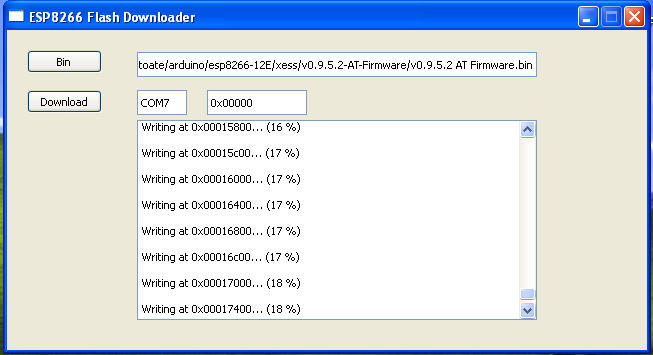
and pus ESP-RST button, firmware will be erased... and this sheild not work, is just a piese untill you reflash the ESP8266 chip.
   I use info from article ESP8266: Reflash Dance! writted by Dave Vandenbout for classic ESP8266:
  Connect USB FTDI interface with 3.3V logic level as in photo
   Must push ESP-RST button and open software
  Find the COM used by USB interface
Change value in software
  Using BIN software button open files
  Using DOWNLOAD software button is write bin files in ESP8266 chip
  In software is writed procent
until is see
   Must change switch position in normal operation mode

   See ESP8266MOD shiled reflash movie, when I made exactlly as in descripription from above