Total Pageviews

Friday, July 8, 2016

Soil moisture control in 4 zones

   For a real garden you need a suystem for soil moisure control in more zones, so, I made a siystem for 4 zones.
   Schematic is simple:
   I write a sketch for this who can download from my channel Github !
   Eatch soil sensor is powered few seconds when measure humidity after that is powerred off (tens of seconds):
- first sensor powered:
- second sensor is powered:
- third sensor is powered:
- fourth sensor is powered:
   You can see two movies:
soil moisture control in 4 zones using Arduino
soil moisture control in 4 zones using Arduino (2)
30.07.2016
   Because are 2 version of relay module:
- with normal control when if you give 5V at input module relay relay is energized and coil is powered, normal open contact is close 
- with negative control (inversed control) when give 5V at input module realy is cut the power at coil, normal open contact is open ...
  So, I put a jumper for easy use of relay modules, when jumper is open (in air) it use normal control and when jumper is close it use negative control.
  Schematic is simple just add jumper:
and must use sketch named lcd1602_i2c_soilhumidity_ver4.ino !

Monday, July 4, 2016

Soil moisture/humidity control system (part 2)

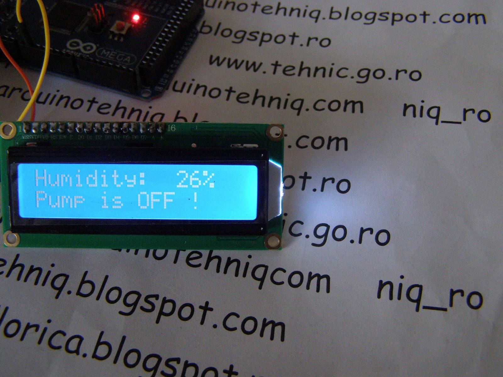
   In previous article I present you a simple metode for read and control soil humidity (soil moisture) and for protect the probe of soil moisture sensor with intermitent power of sensor (just few seconds when measure process - at 5 second whem pump is on for not flooding and at few minutes wheh humidity is ok).
   Now, I put a inportant indication: time elapsed since the last watering process (maximum 999 hours 59 minutes, using millis() soubrotine, see article from https://www.arduino.cc/en/Reference/Millis).
   For that, I use a sketch like lcd1602_i2c_umditatesol_ver2.ino just change texts in english.
   I use same schematic:
   I made 2 movies:
   

Wednesday, June 29, 2016

Soil moisture/humidity control system

   Helpfull for home is a soil moisture control system, who can made easy with a Arduino development board.
   For tests I use a Arduino Mega board, alpahanumerical 1602 LCD with i2c interface, soil moisture module, but for real use must use relay module for control a wattering pump.
   I use sketch named lcd1602_i2c_soilhumidity_ver1.ino who can find at my Github channel.
   My soil moisture sensor is not permanent powered with 5V because in timp probe sensor will be distroyed by electrocorrosion effects, so, I powered the sensor just few seconds at 5 seconds when pump is on for avoid flooding and at 5 minutes (in test I use 20 seconds) when soil is wet.
   I made a few years ago some tests with CMOS 4093 gates (see original article from  http://www.arduinotehniq.com/old/udare_automata/udare_automata_flori.htm) when I use this schematic whit permanent power of soil probe:
and after 3 months my stainess steel probe was corroded:
   So, I put a threshold value at 25% and I have 2 cases:
- when soil is wet, pump is off, measurements are made at long periods:
- when soil is dry, pump is on, measurement are made at 5 seconds for avoid floods:
   You can see these cases in a movie named soil moisture control system using Arduino

Soil moisture (humidity) control system

   Helpfull for home is a soil moisture control system, who can made easy with a Arduino development board.
   For tests I use a Arduino Mega board, alpahanumerical 1602 LCD with i2c interface, soil moisture module, but for real use must use relay module for control a wattering pump.
   I use sketch named lcd1602_i2c_soilhumidity_ver1.ino who can find at my Github channel.
   Soil moisture sensor is very chip
and has this schematic:
   My soil moisture sensor is not permanent powered with 5V because in timp probe sensor will be distroyed by electrocorrosion effects, so, I powered the sensor just few seconds at 5 seconds when pump is on for avoid flooding and at 5 minutes (in test I use 20 seconds) when soil is wet.
   I made a few years ago some tests with CMOS 4093 gates (see original article from  http://www.arduinotehniq.com/old/udare_automata/udare_automata_flori.htm) when I use this schematic whit permanent power of soil probe:
and after 3 months my stainess steel probe was corroded:
   So, I put a threshold value at 25% and I have 2 cases:
- when soil is wet, pump is off, measurements are made at long periods:
- when soil is dry, pump is on, measurement are made at 5 seconds for avoid floods:
   You can see these cases in a movie named soil moisture control system using Arduino

Thursday, June 23, 2016

Soil moisture (humidity) measure system

   A nice and interesting gadget for Arduino board is soil moisture sensor, who can buy from Sparkfun,
ebay, aliexpressbanggood, etc.
   For last version schematic is:
   This version has 2 outputs, one analogical and one digial. If value of humidity is bigger than reference led D2 is on:
   I use a LCD1602 with i2c interface with a Arduino Mega (ADK) board and my test schematic is:
   I write a sketch named lcd1602_i2c_soilhumidity_ver0.ino put on my github channel:
   If sensor has probe in the air:
and if I put wet fingers:

and than I put a clone Arduino Uno board:
   Next step was to I use a Arduino Leonardo:

Monday, June 13, 2016

Arduino on VGA display


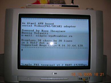
   I search for info about how can use Arduino as VGA tester or video card.
   First credible article is Simple VGA/Video adapter who can use 8-bit AVR MCU like ATmega8, 328, etc:
   Article is writted by Maxx Ibragmov and a their montage is:
   On TV, resolution is 20 rows with 38 character each:
and on VGA monotor, resolution is 20 rows with 20 characters each:
  I wanted fast result and try other adapter montage (without diodes):

   First test was with info from article Arduino generated VGA (color) signal - Complete!
who use this schematic:
   I use Arduino IDE 1.0.3 and my test image is:

NOTE (27.09.2017): Now site is "down", so you can download usefull files from https://github.com/LaboratorioDeGaragem/VGA-com-Arduino !

   I try to reproduce a more complex image like in article Arduino generated VGA (color) signal - Complete! (other site, same author):
but image is not clean.. and I jump to other material find in article Basic Arduino VGA:
   I use same Arduino IDE 1.0.3, but my test image is not same in original article:
   Next step was to reproduce expermiments from Nick Gammon with VGA
   First is a black/white VGA video card for 30 rows with 20 alphanumerical characters each. Schematic is simple:
   This VGA video card use i2c protocol for comunicate with other Arduino board, but results are very poor on transmision data (author say: unfortunately incoming data (can) make  the display "glitch"). I made a movie (explanations are in Romanian language, but you may can understund what I want to say):

   Next test was with moving colour test image on VGA display, using this schematic:
and a image is:
   I made a movie with image on VGA (saame, with explanations are in Romanian language):
   Next step was to test VGAX library writted by Sandro Maffioda after Nick Gammon info.. on display resolution is 120x60px with 4 colours.
   Schematic is simple:
   You can made some combination:
1) red & green made: black, red, green & yellow:
2) red & blue made: black, red, blue, purple:

3) green & blue made: black, green, blue, cyan:
4) red & cyan (green + blue) made: black, red, cyan, white:
5) blue & yellow (red + green) made: black, yellow, blue, white:

6) green & purple (red + blue) made: black, green, purple, white:
   I made some movies for understund more easy: