Dragos, known under albasete name from elforum (romanian electronic forum) made an useful power supply unit. Schemtic used by albasete is
Original schemtic is from Reber electronic site (3A NAPAJALNIK NASTAVLJIV OD 1V DO 27V article). Also, I found same data in article 1V-27V 3A Variable DC Power Supply (http://powersupply33.com/).
For measure voltage and current it use info from Arduino ca multimetru (3). It use existing resistor for measure current (R5) and add 2 resistor as divider resistor for measure voltage:
Using original PCB board, I draw connexion to Arduino board:
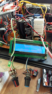
It use an Arduino nano board with i2c LCD1602 display, a active buzzer for indicate shortcircuit case. Also, I put DS18B20 temperature sensor and relay for power a cooler when tenmperature is bigger than a threshold level.
For albasete version, I write psu_reber_ver3ro.ino sketch. In this sketch I put value for albasete case (R1 = 1k put between GND and A1 port, R2 = 39k put between +OUT and A1)
and value for threshold (temax) and hysteresis value (dete):
Now, I put few photo pictures of realization progress:
Dragos (albasete) send me a movie with PSU in tests: 0-30V/0-7A PSU with LM723 and Arduino volt & ampermeter


Could you please send me the code file by email, because the code above is wrong, thanks . Email: nguyenthanhhung2005@gmail.com
ReplyDeletecode is not wrong... you not use same library like me, see library what I use https://github.com/tehniq3/used_library
DeleteMy psu cannot start on 0volt,
ReplyDeleteoutput voltage depends by P2 potentiometer, Arduino is just for measuremets (voltage and current)
DeleteMy psu cannot start on 0volt
ReplyDeletewhat is minimum value at output? output voltage depends by position of P2 potentiometer, maximum current at output depend by position of P1 potentiom,eter...
DeleteSo nice,I always buy some PCB from this company PCBGOGO
ReplyDeletehttps://www.pcbgogo.com/?code=y
Hey man can you send me the code your given code is not working gives error.
ReplyDeleteMy email : Huaweimoboile@gmail.com
Thanks in advance
Code gives error on lcd.begin
ReplyDeletedowload lcd library from here: https://github.com/tehniq3/used_library
DeleteWork principal of amp and volts
ReplyDeleteWhen compiling this error
ReplyDeletelcd.begin(); // initializare afisaj
no matching function for call to 'LiquidCrystal_I2C::begin()'
I use library from https://github.com/fdebrabander/Arduino-LiquidCrystal-I2C-library
DeleteThis library is put also at https://github.com/tehniq3/used_library
thanks a lot you are good man
Deletei use lcd.init();
Deletethanks
Bonjour ,
ReplyDeleteMalgré vos recommandations pour télécharger la librairie i2c , j'ai toujours l'erreur lcd.begin , au secours pouvez vous m'aider . merci
Cdlt Alan/f1lqn radio amateur (France)
diwnload zip file from https://github.com/tehniq3/used_library and extract and use library for display
DeleteBom dia o programa tem erros de palavras.
ReplyDeletetrcurent flutuante = 0 ;
informação do erro 'trcurent' does not name a type
Bom dia o programa tem erros de palavras.
ReplyDeletetrcurent flutuante = 0 ;
'trcurent' does not name a type
you must use original sketch not translated sketch by google
Deleteif (tensiune < 0,8 ) // scurtcircuit
Delete{
lcd. setCursor ( 9 , 0 );
lcd. imprimir ( " scurt " );
digitalWrite (tiuitoare, HIGH);
atraso ( 100 );
}
senão
{
lcd. setCursor ( 9 , 0 );
lcd. imprimir ( " " );
}
senão também é valido?
this part is for shoetcircuit... if you read in your language zi will replay in my language 😎 if you want clear answer please use english
DeleteSensores de temperatura Dallas (& oneWire);
ReplyDelete'Sensores' does not name a type; did you mean 'Sensor'?
Sensores dá-me erro:
you must have all libraries from sketch...
DeleteWhere can buy Corsair RM650 650 Watt 80 PLUS Gold Fully Modular Power Supply in Uae
ReplyDeletehttps://pcdubai.com/product/corsair-rm650-650-watt-80-plus-gold-fully-modular-power-supply-cp-9020194-uk/
Congratulations for the project
ReplyDeleteCould you please send me the code file by email
dmarucci@abril.com.br
no, you can fownload from Github as other readers of my blog: https://github.com/tehniq3/PS_reber/blob/master/psu_reber_ver3ro.ino
Delete*fownload = download
DeleteHi,
ReplyDeleteThis is a very nice project. I would like to build just the Arduino V/A meter in order to use it with my already built PS and I have a question regarding the current sensing resistor (R5 or Rs in your schematic): Although in your schematic R5 is designated as 0R15, in the sketch it is set at 0R055 {float rsunt = 0.055 ; // valoare rezistenta (sunt)}, which is the value of the first schematic you site (albasete's original schematic).
So, I have the following question: which is the correct value for R5. Or, else, can I put my preferred value and set the same value in the sketch?
Thank you!
you need to put real value of shunt resistor
DeleteIn your implementation, what is the value of the shunt resistor, 0R15 or 0R055?
Deleteplease, consider to write correct value for shunt... now power supply fron this article is not mine... I can't check...
DeleteNice blog. Thanks for sharing. Keep sharing!!
ReplyDeleteBuy TFT LCD Panels