


Note: Battery is CR2032, like in schematic... in boards is a little error
A full schematic for RTC clock with Arduino is:
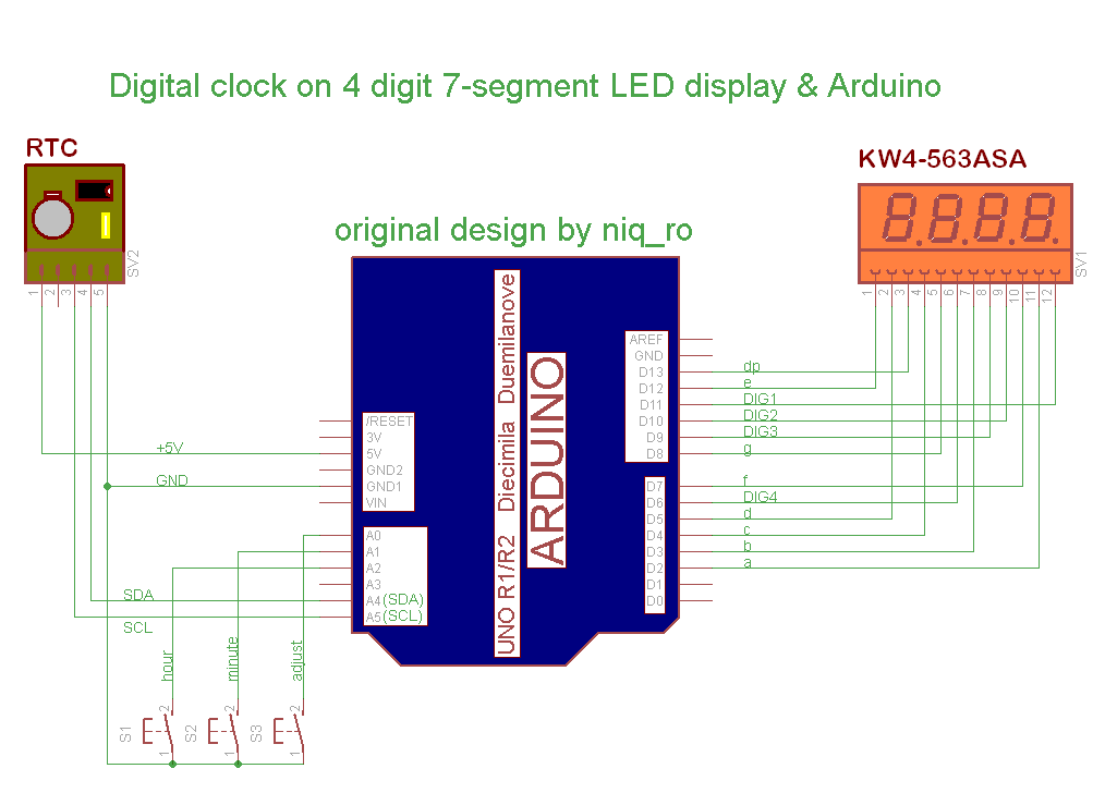
Compared to other schematics that can adjust time (reset clock at 0:00, adjust hours and minutes). Original schematic, design and sketch is from article Using Arduino with a DS1307 Real Time Clock by Lewis Loflin.
If you want to change time, must push and hold S3 (adjust) switch and display is change on 0:00, then push S1 (hour) or S2 (minute) repeatedly until time is ok, after this realise S3, and time is put in RTC.
I use a multiplexed 4-digit 7-segment display with common anode same in article named Arduino UNO running 4-digit 7-segment display from http://www.hobbytronics.co.uk/. Is a unusual schematic, but works fine; a usual schematic use resistors for current limit.

My sketch is:
/*
 4 digit 7 segment display: http://www.sparkfun.com/products/9483
 Datasheet: http://www.sparkfun.com/datasheets/Components/LED/7-Segment/YSD-439AR6B-35.pdf
 7 segments + 4 digits + 1 colon = 12 pins required for full control
 */
// modified connexion by niq_ro from http://nicuflorica.blogspot.com
// for my Luckylight KW4-563ASA
// dataseet: http://www.tme.eu/ro/Document/dfc2efde2e22005fd28615e298ea2655/KW4-563XSA.pdf

int digit1 = 11; //PWM Display pin 12 (digit1 is common anonds A1 from right side)
int digit2 = 10; //PWM Display pin 9 (digit2 is  common A2)
int digit3 = 9; //PWM Display pin 8 (digit3 is common anods A3)
int digit4 = 6; //PWM Display pin 6 (digit4 is common anods, from left side)

//Pin mapping from Arduino to the ATmega DIP28 if you need it
//http://www.arduino.cc/en/Hacking/PinMapping
int segA = 2; //Display pin 11
int segB = 3; //Display pin 7
int segC = 4; //Display pin 4
int segD = 5; //Display pin 2
int segE = 12; //Display pin 1
int segF = 7; //Display pin 10
int segG = 8; //Display pin 5
int segDP = 13; // Display pin 3

#include <Wire.h>
#include "RTClib.h"
RTC_DS1307 RTC;

// Date and time functions using a DS1307 RTC connected via I2C and Wire lib
// original sketck from http://learn.adafruit.com/ds1307-real-time-clock-breakout-board-kit/
// add part with SQW=1Hz from http://tronixstuff.wordpress.com/2010/10/20/tutorial-arduino-and-the-i2c-bus/
// add part with manual adjust http://www.bristolwatch.com/arduino/arduino_ds1307.htm


byte SW0 = A0;
byte SW1 = A1;
byte SW2 = A2;

// use for hexa in zecimal conversion
int zh, uh, ore;
int zm, um, miniti;

void setup() {

 //  Serial.begin(57600);
  Wire.begin();
  RTC.begin();
// RTC.adjust(DateTime(__DATE__, __TIME__));
// if you need set clock... just remove // from line above this

// part code for flashing LED
Wire.beginTransmission(0x68);
Wire.write(0x07); // move pointer to SQW address
// Wire.write(0x00); // turns the SQW pin off
 Wire.write(0x10); // sends 0x10 (hex) 00010000 (binary) to control register - turns on square wave at 1Hz
// Wire.write(0x13); // sends 0x13 (hex) 00010011 (binary) 32kHz

Wire.endTransmission();

  if (! RTC.isrunning()) {
    Serial.println("RTC is NOT running!");
    // following line sets the RTC to the date & time this sketch was compiled
    RTC.adjust(DateTime(__DATE__, __TIME__));
  }


// dht.begin();

  pinMode(segA, OUTPUT);
  pinMode(segB, OUTPUT);
  pinMode(segC, OUTPUT);
  pinMode(segD, OUTPUT);
  pinMode(segE, OUTPUT);
  pinMode(segF, OUTPUT);
  pinMode(segG, OUTPUT);
  pinMode(segDP, OUTPUT);

  pinMode(digit1, OUTPUT);
  pinMode(digit2, OUTPUT);
  pinMode(digit3, OUTPUT);
  pinMode(digit4, OUTPUT);

//  pinMode(13, OUTPUT);

 Serial.begin(9600);
 Serial.println("test for niq_ro");

 pinMode(SW0, INPUT);  // for this use a slide switch
  pinMode(SW1, INPUT);  // N.O. push button switch
  pinMode(SW2, INPUT);  // N.O. push button switch

  digitalWrite(SW0, HIGH); // pull-ups on
  digitalWrite(SW1, HIGH);
  digitalWrite(SW2, HIGH);


}

void loop() {
digitalWrite(segDP, HIGH);
  DateTime now = RTC.now();
  int timp = now.hour()*100+now.minute();
//   int timp = (now.minute(), DEC);
//   displayNumber(12); // this is number to diplay
//   int timp = 1234;
  Serial.print(now.hour(), DEC);
  Serial.print(":");
  Serial.print(now.minute(), DEC);
  Serial.print(" -> ");
  Serial.print(timp);
  Serial.println(" !");

// display parts
   for(int i = 250 ; i >0  ; i--) {
     if (timp >= 1000) displayNumber01(timp);
     else displayNumber02(timp);
   }

   for(int i = 250 ; i >0  ; i--) {
     if (timp >= 1000) displayNumber03(timp);
     else displayNumber04(timp);
   }

  if (!(digitalRead(SW0))) set_time(); // hold the switch to set time
}


void set_time()   {
  byte minutes1 = 0;
  byte hours1 = 0;
  byte minutes = 0;
  byte hours = 0;

  while (!digitalRead(SW0))  // set time switch must be released to exit
  {
    minutes1=minutes;
    hours1=hours;


    while (!digitalRead(SW1)) // set minutes
    {
     minutes++;
   // converting hexa in zecimal:
    zh = hours / 16;
    uh = hours - 16 * zh ;
    ore = 10 * zh + uh;
    zm = minutes / 16;
    um = minutes - 16 * zm ;
    miniti = 10 * zm + um;

     for(int i = 20 ; i >0  ; i--) {
     displayNumber01(ore*100+miniti);
     }


      if ((minutes & 0x0f) > 9) minutes = minutes + 6;
      if (minutes > 0x59) minutes = 0;
      Serial.print("Minutes = ");
      if (minutes >= 9) Serial.print("0");
      Serial.println(minutes, HEX);
    delay(150);
    }

    while (!digitalRead(SW2)) // set hours
    {
     hours++;

   // converting hexa in zecimal:
    zh = hours / 16;
    uh = hours - 16 * zh ;
    ore = 10 * zh + uh;
    zm = minutes / 16;
    um = minutes - 16 * zm ;
    miniti = 10 * zm + um;

     for(int i = 20 ; i >0  ; i--) {
     displayNumber01(ore*100+miniti);
     }


      if ((hours & 0x0f) > 9) hours =  hours + 6;
      if (hours > 0x23) hours = 0;
      Serial.print("Hours = ");
      if (hours <= 9) Serial.print("0");
      Serial.println(hours, HEX);
    delay(150);
    }

    Wire.beginTransmission(0x68); // activate DS1307
    Wire.write(0); // where to begin
    Wire.write(0x00);          //seconds
    Wire.write(minutes);          //minutes
    Wire.write(0x80 | hours);    //hours (24hr time)
    Wire.write(0x06);  // Day 01-07
    Wire.write(0x01);  // Date 0-31
    Wire.write(0x05);  // month 0-12
    Wire.write(0x09);  // Year 00-99
    Wire.write(0x10); // Control 0x10 produces a 1 HZ square wave on pin 7.
    Wire.endTransmission();

    // converting hexa in zecimal:
    zh = hours / 16;
    uh = hours - 16 * zh ;
    ore = 10 * zh + uh;
    zm = minutes / 16;
    um = minutes - 16 * zm ;
    miniti = 10 * zm + um;

     for(int i = 20 ; i >0  ; i--) {
     displayNumber01(ore*100+miniti);
     }
 //  delay(150);

  }

}


void displayNumber01(int toDisplay) {
#define DISPLAY_BRIGHTNESS  500

#define DIGIT_ON  HIGH
#define DIGIT_OFF  LOW

  for(int digit = 4 ; digit > 0 ; digit--) {

    //Turn on a digit for a short amount of time
    switch(digit) {
    case 1:
     digitalWrite(digit1, DIGIT_ON);
     digitalWrite(segDP, HIGH);
      break;
   case 2:
      digitalWrite(digit2, DIGIT_ON);
      digitalWrite(segDP, LOW);
      break;
    case 3:
      digitalWrite(digit3, DIGIT_ON);
      digitalWrite(segDP, HIGH);
      break;
    case 4:
      digitalWrite(digit4, DIGIT_ON);
      digitalWrite(segDP, HIGH);
      break;
    }
    lightNumber(toDisplay % 10);
    toDisplay /= 10;
    delayMicroseconds(DISPLAY_BRIGHTNESS);

     //Turn off all segments
    lightNumber(10);

    //Turn off all digits
    digitalWrite(digit1, DIGIT_OFF);
    digitalWrite(digit2, DIGIT_OFF);
    digitalWrite(digit3, DIGIT_OFF);
    digitalWrite(digit4, DIGIT_OFF);
}
}

void displayNumber02(int toDisplay) {
#define DISPLAY_BRIGHTNESS  500

#define DIGIT_ON  HIGH
#define DIGIT_OFF  LOW

  for(int digit = 4 ; digit > 0 ; digit--) {

    //Turn on a digit for a short amount of time
    switch(digit) {
    case 1:
     lightNumber(10);
     digitalWrite(segDP, HIGH);
     break;
   case 2:
      digitalWrite(digit2, DIGIT_ON);
      digitalWrite(segDP, LOW);
      break;
    case 3:
      digitalWrite(digit3, DIGIT_ON);
      digitalWrite(segDP, HIGH);
      break;
    case 4:
      digitalWrite(digit4, DIGIT_ON);
      digitalWrite(segDP, HIGH);
      break;
    }
    lightNumber(toDisplay % 10);
    toDisplay /= 10;
    delayMicroseconds(DISPLAY_BRIGHTNESS);

     //Turn off all segments
    lightNumber(10);

    //Turn off all digits
    digitalWrite(digit1, DIGIT_OFF);
    digitalWrite(digit2, DIGIT_OFF);
    digitalWrite(digit3, DIGIT_OFF);
    digitalWrite(digit4, DIGIT_OFF);
}
}

void displayNumber03(int toDisplay) {
#define DISPLAY_BRIGHTNESS  500

#define DIGIT_ON  HIGH
#define DIGIT_OFF  LOW

  for(int digit = 4 ; digit > 0 ; digit--) {

    //Turn on a digit for a short amount of time
    switch(digit) {
    case 1:
     digitalWrite(digit1, DIGIT_ON);
     digitalWrite(segDP, HIGH);
      break;
   case 2:
      digitalWrite(digit2, DIGIT_ON);
      digitalWrite(segDP, HIGH);
      break;
    case 3:
      digitalWrite(digit3, DIGIT_ON);
      digitalWrite(segDP, HIGH);
      break;
    case 4:
      digitalWrite(digit4, DIGIT_ON);
      digitalWrite(segDP, HIGH);
      break;
    }
    lightNumber(toDisplay % 10);
    toDisplay /= 10;
    delayMicroseconds(DISPLAY_BRIGHTNESS);

     //Turn off all segments
    lightNumber(10);

    //Turn off all digits
    digitalWrite(digit1, DIGIT_OFF);
    digitalWrite(digit2, DIGIT_OFF);
    digitalWrite(digit3, DIGIT_OFF);
    digitalWrite(digit4, DIGIT_OFF);
}
}

void displayNumber04(int toDisplay) {
#define DISPLAY_BRIGHTNESS  500

#define DIGIT_ON  HIGH
#define DIGIT_OFF  LOW

  for(int digit = 4 ; digit > 0 ; digit--) {

    //Turn on a digit for a short amount of time
    switch(digit) {
    case 1:
     lightNumber(10);
     digitalWrite(segDP, HIGH);
     break;
   case 2:
      digitalWrite(digit2, DIGIT_ON);
      digitalWrite(segDP, HIGH);
      break;
    case 3:
      digitalWrite(digit3, DIGIT_ON);
      digitalWrite(segDP, HIGH);
      break;
    case 4:
      digitalWrite(digit4, DIGIT_ON);
      digitalWrite(segDP, HIGH);
      break;
    }
    lightNumber(toDisplay % 10);
    toDisplay /= 10;
    delayMicroseconds(DISPLAY_BRIGHTNESS);

     //Turn off all segments
    lightNumber(10);

    //Turn off all digits
    digitalWrite(digit1, DIGIT_OFF);
    digitalWrite(digit2, DIGIT_OFF);
    digitalWrite(digit3, DIGIT_OFF);
    digitalWrite(digit4, DIGIT_OFF);
}
}


//Given a number, turns on those segments
//If number == 10, then turn off number
void lightNumber(int numberToDisplay) {

#define SEGMENT_ON  LOW
#define SEGMENT_OFF HIGH

  switch (numberToDisplay){

  case 0:
    digitalWrite(segA, SEGMENT_ON);
    digitalWrite(segB, SEGMENT_ON);
    digitalWrite(segC, SEGMENT_ON);
    digitalWrite(segD, SEGMENT_ON);
    digitalWrite(segE, SEGMENT_ON);
    digitalWrite(segF, SEGMENT_ON);
    digitalWrite(segG, SEGMENT_OFF);
    break;

  case 1:
    digitalWrite(segA, SEGMENT_OFF);
    digitalWrite(segB, SEGMENT_ON);
    digitalWrite(segC, SEGMENT_ON);
    digitalWrite(segD, SEGMENT_OFF);
    digitalWrite(segE, SEGMENT_OFF);
    digitalWrite(segF, SEGMENT_OFF);
    digitalWrite(segG, SEGMENT_OFF);
    break;

  case 2:
    digitalWrite(segA, SEGMENT_ON);
    digitalWrite(segB, SEGMENT_ON);
    digitalWrite(segC, SEGMENT_OFF);
    digitalWrite(segD, SEGMENT_ON);
    digitalWrite(segE, SEGMENT_ON);
    digitalWrite(segF, SEGMENT_OFF);
    digitalWrite(segG, SEGMENT_ON);
    break;

  case 3:
    digitalWrite(segA, SEGMENT_ON);
    digitalWrite(segB, SEGMENT_ON);
    digitalWrite(segC, SEGMENT_ON);
    digitalWrite(segD, SEGMENT_ON);
    digitalWrite(segE, SEGMENT_OFF);
    digitalWrite(segF, SEGMENT_OFF);
    digitalWrite(segG, SEGMENT_ON);
    break;

  case 4:
    digitalWrite(segA, SEGMENT_OFF);
    digitalWrite(segB, SEGMENT_ON);
    digitalWrite(segC, SEGMENT_ON);
    digitalWrite(segD, SEGMENT_OFF);
    digitalWrite(segE, SEGMENT_OFF);
    digitalWrite(segF, SEGMENT_ON);
    digitalWrite(segG, SEGMENT_ON);
    break;

  case 5:
    digitalWrite(segA, SEGMENT_ON);
    digitalWrite(segB, SEGMENT_OFF);
    digitalWrite(segC, SEGMENT_ON);
    digitalWrite(segD, SEGMENT_ON);
    digitalWrite(segE, SEGMENT_OFF);
    digitalWrite(segF, SEGMENT_ON);
    digitalWrite(segG, SEGMENT_ON);
    break;

  case 6:
    digitalWrite(segA, SEGMENT_ON);
    digitalWrite(segB, SEGMENT_OFF);
    digitalWrite(segC, SEGMENT_ON);
    digitalWrite(segD, SEGMENT_ON);
    digitalWrite(segE, SEGMENT_ON);
    digitalWrite(segF, SEGMENT_ON);
    digitalWrite(segG, SEGMENT_ON);
    break;

  case 7:
    digitalWrite(segA, SEGMENT_ON);
    digitalWrite(segB, SEGMENT_ON);
    digitalWrite(segC, SEGMENT_ON);
    digitalWrite(segD, SEGMENT_OFF);
    digitalWrite(segE, SEGMENT_OFF);
    digitalWrite(segF, SEGMENT_OFF);
    digitalWrite(segG, SEGMENT_OFF);
    break;

  case 8:
    digitalWrite(segA, SEGMENT_ON);
    digitalWrite(segB, SEGMENT_ON);
    digitalWrite(segC, SEGMENT_ON);
    digitalWrite(segD, SEGMENT_ON);
    digitalWrite(segE, SEGMENT_ON);
    digitalWrite(segF, SEGMENT_ON);
    digitalWrite(segG, SEGMENT_ON);
    break;

  case 9:
    digitalWrite(segA, SEGMENT_ON);
    digitalWrite(segB, SEGMENT_ON);
    digitalWrite(segC, SEGMENT_ON);
    digitalWrite(segD, SEGMENT_ON);
    digitalWrite(segE, SEGMENT_OFF);
    digitalWrite(segF, SEGMENT_ON);
    digitalWrite(segG, SEGMENT_ON);
    break;

  // all segment are ON
  case 10:
    digitalWrite(segA, SEGMENT_OFF);
    digitalWrite(segB, SEGMENT_OFF);
    digitalWrite(segC, SEGMENT_OFF);
    digitalWrite(segD, SEGMENT_OFF);
    digitalWrite(segE, SEGMENT_OFF);
    digitalWrite(segF, SEGMENT_OFF);
    digitalWrite(segG, SEGMENT_OFF);
    break;

  }
}
I made a litle movie named manual adjust for RTC clock with Arduino and 7-segment LED display
Note: Original article in roumanian language is Afisaje LED cu 7 segmente si.. Arduino (IV)!!!
I correct sketch for display 10:00 case..

07.02.2017
Now, I pun on my Github channel sketch for cathode comon display, see github.com/tehniq3/multiplexedclock
sketch why can not store a position to continue?
ReplyDeletereset back in position even when uploading code
you must comment line:
DeleteRTC.adjust(DateTime(__DATE__, __TIME__));
// if you need set clock... just remove // from line above this
===>
// RTC.adjust(DateTime(__DATE__, __TIME__));
// if you need set clock... just remove // from line above this
ok, the code works great. Thank you.
DeleteGod bless you
how to driving a large 7 segment CA / 12volt ?
ReplyDeleteyou must using pnp transistors for common anode and npn transistors for segments.. just use GOOGLE SEARCH
ReplyDeletenot work perfect. must make ic hex converter. do you know this ic ?
Delete1) work good for me...
Delete2) if you use Arduino board you cand you cand upload sketh directly...
3) if you want to put a hex in ATmega328P-PU at 16MHz, I cat put a hex file.. but I want to see first the article from http://www.jameco.com/Jameco/workshop/JamecoBuilds/arduinocircuit.html?CID=arduinobuild and after you read.. I wait you "review"
i made it, on breadboard with 0,36" 7 segment clock from your sketch. it's perfectly. i am publishing in youtube : https://youtu.be/IHLKxl0Hk0s
Deletefurthermore, I want to enlarge a digital clock with a 3 inch 7 segment, but not perfect or all segments lit all. became number 8 continues without following the digclock small (0.36 ")
Deletehow to upload photos on this blog?
Deleteyou can't upload directlly photos in blog, but you have 2 ways:
Delete1) you put photo on free server like http://tinypic.com/ and than you put link in "replay",
2) send me photos and if I like them, I put in article with your name in comment
http://tinypic.com/2mpmn505
Deletemy first video . Can you solve the problem ?
how to maximal brightness ?
ReplyDeletevoid displayNumber01(int toDisplay) {
#define DISPLAY_BRIGHTNESS 500
#define DIGIT_ON HIGH
#define DIGIT_OFF LOW
for(int digit = 4 ; digit > 0 ; digit--) {
//Turn on a digit for a short amount of time
switch(digit) {
case 1:
digitalWrite(digit1, DIGIT_ON);
digitalWrite(segDP, HIGH);
break;
case 2:
digitalWrite(digit2, DIGIT_ON);
digitalWrite(segDP, LOW);
break;
case 3:
digitalWrite(digit3, DIGIT_ON);
digitalWrite(segDP, HIGH);
break;
case 4:
digitalWrite(digit4, DIGIT_ON);
digitalWrite(segDP, HIGH);
break;
}
lightNumber(toDisplay % 10);
toDisplay /= 10;
delayMicroseconds(DISPLAY_BRIGHTNESS);
//Turn off all segments
lightNumber(10);
//Turn off all digits
digitalWrite(digit1, DIGIT_OFF);
digitalWrite(digit2, DIGIT_OFF);
digitalWrite(digit3, DIGIT_OFF);
digitalWrite(digit4, DIGIT_OFF);
}
}
void displayNumber02(int toDisplay) {
#define DISPLAY_BRIGHTNESS 500
#define DIGIT_ON HIGH
#define DIGIT_OFF LOW
for(int digit = 4 ; digit > 0 ; digit--) {
//Turn on a digit for a short amount of time
switch(digit) {
case 1:
lightNumber(10);
digitalWrite(segDP, HIGH);
break;
case 2:
digitalWrite(digit2, DIGIT_ON);
digitalWrite(segDP, LOW);
break;
case 3:
digitalWrite(digit3, DIGIT_ON);
digitalWrite(segDP, HIGH);
break;
case 4:
digitalWrite(digit4, DIGIT_ON);
digitalWrite(segDP, HIGH);
break;
}
lightNumber(toDisplay % 10);
toDisplay /= 10;
delayMicroseconds(DISPLAY_BRIGHTNESS);
//Turn off all segments
lightNumber(10);
//Turn off all digits
digitalWrite(digit1, DIGIT_OFF);
digitalWrite(digit2, DIGIT_OFF);
digitalWrite(digit3, DIGIT_OFF);
digitalWrite(digit4, DIGIT_OFF);
}
}
where numbers need to be changed ?
Thanks verymuch
my sketches are based on http://cdn.sparkfun.com/datasheets/Components/LED/_7Seg_Example.pde sketch and inside is text:
ReplyDelete"//Display brightness
//Each digit is on for a certain amount of microseconds
//Then it is off until we have reached a total of 20ms for the function call
//Let's assume each digit is on for 1000us
//If each digit is on for 1ms, there are 4 digits, so the display is off for 16ms.
//That's a ratio of 1ms to 16ms or 6.25% on time (PWM).
//Let's define a variable called brightness that varies from:
//5000 blindingly bright (15.7mA current draw per digit)
//2000 shockingly bright (11.4mA current draw per digit)
//1000 pretty bright (5.9mA)
//500 normal (3mA)
//200 dim but readable (1.4mA)
//50 dim but readable (0.56mA)
//5 dim but readable (0.31mA)
//1 dim but readable in dark (0.28mA) "
for me and my Arduino board is ok 500 as maximum value for display brightness.. you can test bigger value...
ok, thank you very much.
ReplyDeleteI try brightness of 5000, but no effect in all 7 segment. Second / dot lights up to 5 seconds, 5 seconds off.
I want to try some of your tutorial. very nice
where this article ?
ReplyDelete// adapted sketch by niq_ro from http://arduinotehniq.blogspot.com
// and http://nicuflorica.blogspot.ro
// base version 1.0 in 6.11.2014, Craiova - Romanaia
// actul version 3.0 in 22.05.2015
// source for LEDControl: http://embedded-lab.com/blog/?p=6862
#include "LedControl.h"
/*
Now we need a LedControl to work with.
***** These pin numbers will probably not work with your hardware *****
pin 12 is connected to the DataIn
pin 11 is connected to the CLK
pin 10 is connected to LOAD
We have only a single MAX72XX.
*/
LedControl lc=LedControl(12,11,10,1);
// Example testing sketch for various DHT humidity/temperature sensors
// Written by ladyada, public domain
#include "DHT.h"
#define DHTPIN A1 // what pin we're connected to A1
// Uncomment whatever type you're using!
//#define DHTTYPE DHT11 // DHT 11
#define DHTTYPE DHT22 // DHT 22 (AM2302)
//#define DHTTYPE DHT21 // DHT 21 (AM2301)
// if is just sensor:
// Connect pin 1 (on the left) of the sensor to +5V
// Connect pin 2 of the sensor to whatever your DHTPIN is
// Connect pin 4 (on the right) of the sensor to GROUND
// Connect a 10K resistor from pin 2 (data) to pin 1 (power) of the sensor
DHT dht(DHTPIN, DHTTYPE);
// declaration for type of value
float t, h, t1;
// Date and time functions using a DS1307 RTC connected via I2C and Wire lib
// original sketck from http://learn.adafruit.com/ds1307-real-time-clock-breakout-board-kit/
// add part with SQW=1Hz from http://tronixstuff.wordpress.com/2010/10/20/tutorial-arduino-and-the-i2c-bus/
// Dawn & Dusk controller. http://andydoz.blogspot.ro/2014_08_01_archive.html
// 16th August 2014 - (C) A.G.Doswell 2014
#include
#include "RTClib.h" // from https://github.com/adafruit/RTClib
#include
#include // from http://www.pjrc.com/teensy/td_libs_Encoder.html
I don't understund your problem... I you have time, see alse base blog: http://nicuflorica.blogspot.ro/ ;)
DeleteHow can I make this as 12 hour clock (not 24 as it is)
ReplyDeleteI not have all project libve, but you can see http://www.avrfreaks.net/forum/ds1307-enabling-12-hour-solved-working-code
ReplyDeleteHi.
ReplyDeleteI just tried to builde clock and I have problem. After wired and upload sketch to arduino I see on the display 66.65 with blinking dot for all the time.
After presing S3 i see 00.00 and I can modyfi that value by pressing S1 and s2 buton, but after relice S3 display come back to 66.65.
Do anyone have any ide what go wrong?
THX in advance for any answer
I think your RTC clock in not correct put at Arduino...
DeleteArduino: 1.6.8 (Windows 10), Board: "Arduino/Genuino Uno"
ReplyDeleteC:\Users\Krisna\Documents\Arduino\DIGITALCLOCK\DIGITALCLOCK.ino:27:20: fatal error: RTClib.h: No such file or directory
#include "RTClib.h"
^
compilation terminated.
exit status 1
Error compiling for board Arduino/Genuino Uno.
This report would have more information with
"Show verbose output during compilation"
option enabled in File -> Preferences.
?????
you haven't RTClib library... try to use google search.. see https://github.com/adafruit/RTClib
Deletehello please am new to this Arduino can u please send me the full code of this clock for me to try it
ReplyDeletefull sketch is in article, after text "My sketch is:"
Deleteplease test first to upload Blink example or some easy.. after that try some difficult like this...
Hi i have try it i won't to do the clock so i need the code please
DeleteI have try this adjustment code and it working i need the full code for the clock please
ReplyDeleteworks... must HOLD the switch SW0 to set time... and push SW1 for hours and SW2 to minutes.. see the movie...
Deleteeverything is working but the code is only for adjustment and i need the full code for the clock and adjustment can you help me out please i will be very grateful
Deleteis full code.. hmm
Deletewhich code please
ReplyDeletein article is just a sketch.. one.. just one sketch...
Deletehow many sketches you see?
one but is only for adjustment of the segment, and i ask if you have the full code of the clock there. i wont to make a digital clock so if you have the code or another schematic and code please help me out. thanks
ReplyDeleteufff... sketch is full, just try it...
Deleteyou try the sketch? you put 3 buttons? push and hold pushed SW0 and push short SW1 or SW2? TRY. TRY, TRY..
please copy sketch what you see... I think you tell about other sketch than me...
whether it can be plus melody (tone) every 1 hour chime? 1 hour rang 1x, 2x reads 2 hours, 3 hours 12 hours reads 3x .... sounds 12x then back to 1
ReplyDeleteyes, can be put.. now i haven't time for tests, but soon I will put a sketch witch with tone at every hours :)
Deletegreat idea, thanks
Deletehello, if i want make Manual adjust for RTC clock with Arduino and 7-segment LED display with shift register can you give sketch.....tanks before
ReplyDeleteHai Nicu FLORICA,
ReplyDeleteThis is a nice project, but could you please to add the program that activate a relay if the time is already reach/set like an alarm ?
Thank You
Nice tutorial..... Thank You,,,,
ReplyDeleteIts Work.
1) unable to set time using RTC
ReplyDelete2) if the time is [ 9:59 ] after 60 seconds it will be remaining as [ 0:00 ] and it
doesn`t displaying the digit 1 in the first segment instead of
displaying [ 10:00 ] and it displays only when the 00 shifted to 01 ,
[ 10:01]
can u help me plz
1) you pust push SW0 button and hold it.. on display mst see 00:00, after that push other buttons for hours and minutes.. it easy...
Delete2) In comment in original article from http://nicuflorica.blogspot.ro/2013/12/afisaje-led-cu-7-segmente-si-arduino-iv.html is same problem, but it easy to change... in sketch are 2 line who must change: if (timp > 1000) displayNumber01(timp); in if (timp >= 1000) displayNumber01(timp);
& if (timp > 1000) displayNumber03(timp); in if (timp >= 1000) displayNumber03(timp); I forgot 10:00 hours :)))
PS: I change sketch for display correct 10:00 hours
Hi help pls. how to fix this
ReplyDeleteD:\Documents\Arduino\sketch_oct10a\sketch_oct10a.ino: In function 'void setup()':
sketch_oct10a:57: error: 'class TwoWire' has no member named 'write'
Wire.write(0x07); // move pointer to SQW address
^
sketch_oct10a:58: error: 'class TwoWire' has no member named 'write'
Wire.write(0x00); // turns the SQW pin off
^
sketch_oct10a:59: error: 'class TwoWire' has no member named 'write'
Wire.write(0x10); // sends 0x10 (hex) 00010000 (binary) to control register - turns on square wave at 1Hz
^
sketch_oct10a:60: error: 'class TwoWire' has no member named 'write'
Wire.write(0x13); // sends 0x13 (hex) 00010011 (binary) 32kHz
^
D:\Documents\Arduino\sketch_oct10a\sketch_oct10a.ino: In function 'void set_time()':
sketch_oct10a:195: error: 'class TwoWire' has no member named 'write'
Wire.write(0); // where to begin
^
sketch_oct10a:196: error: 'class TwoWire' has no member named 'write'
Wire.write(0x00); //seconds
^
sketch_oct10a:197: error: 'class TwoWire' has no member named 'write'
Wire.write(minutes); //minutes
^
sketch_oct10a:198: error: 'class TwoWire' has no member named 'write'
Wire.write(0x80 | hours); //hours (24hr time)
^
sketch_oct10a:199: error: 'class TwoWire' has no member named 'write'
Wire.write(0x06); // Day 01-07
^
sketch_oct10a:200: error: 'class TwoWire' has no member named 'write'
Wire.write(0x01); // Date 0-31
^
sketch_oct10a:201: error: 'class TwoWire' has no member named 'write'
Wire.write(0x05); // month 0-12
^
sketch_oct10a:202: error: 'class TwoWire' has no member named 'write'
Wire.write(0x09); // Year 00-99
^
sketch_oct10a:203: error: 'class TwoWire' has no member named 'write'
Wire.write(0x10); // Control 0x10 produces a 1 HZ square wave on pin 7.
^
Multiple libraries were found for "Wire.h"
Used: D:\Documents\Arduino\libraries\Wire
Not used: D:\Desktop\arduino-1.6.8\hardware\arduino\avr\libraries\Wire
exit status 1
'class TwoWire' has no member named 'write'
you have more libraries with Wire.h... move TwoWire librarie from Libraries directory
ReplyDeletethank you
DeleteThank you for your help.It is one of my college project and the correction you had made in this code helps me a lot for the completion. And this is my first arduino project experience in my life. :))
ReplyDeleteHi how can i make this standalone.
ReplyDeleteyou can use or Arduino Pro Mini board or an ATmega328P-PU microcontroller, like in article http://nicuflorica.blogspot.ro/2014/02/transferarea-unui-proiect-arduino-pe-un.html
Deletethank you.
DeleteThis comment has been removed by the author.
ReplyDeleteHi.
ReplyDeleteIf anyone have any idea how can i do this - I want to make 3 clock that control in one controller, control buttons and 3 clock.
you can try with 3 pcs 74hc541 for anode and 3 pcs 74hc541 for cathode. but it will need a lot of cables
DeleteIts work, I use RTC 3231 and catoda segment. Thank you...
ReplyDeletehellow Nicu FLORICA will you plz tell me how to change 24 hrs in 12 hrs format in your code
ReplyDeleteHi, I haven't time to remade the clock, but I find a interesting Github material, see https://github.com/jarzebski/Arduino-DS1307
DeleteArduino: 1.6.12 (Windows 8.1), Board: "Arduino/Genuino Uno"
ReplyDeleteC:\Users\Maulana\Documents\Arduino\jam_sip\jam_sip.ino: In function 'void setup()':
jam_sip:44: error: request for member 'isrunning' in 'RTC', which is of non-class type 'float'
Serial.print(! RTC.isrunning); {
^
jam_sip:47: error: request for member 'adjust' in 'RTC', which is of non-class type 'float'
RTC.adjust(DateTime(__DATE__, __TIME__));
^
jam_sip:47: error: 'DateTime' was not declared in this scope
RTC.adjust(DateTime(__DATE__, __TIME__));
^
C:\Users\Maulana\Documents\Arduino\jam_sip\jam_sip.ino: In function 'void loop()':
jam_sip:86: error: 'DateTime' was not declared in this scope
DateTime now = RTC.now();
^
jam_sip:87: error: 'now' was not declared in this scope
int timp = now.hour()*100+now.minute();
^
exit status 1
request for member 'isrunning' in 'RTC', which is of non-class type 'float'
This report would have more information with
"Show verbose output during compilation"
option enabled in File -> Preferences.
?????
you have RTClib library ?
Deleteif you have RTClib, try an old version on Arduino IDE 1.0.3..1.0.5... this version just download and work as portablw software and not distroy new version (1.6.12 in your case)
ReplyDeleteSir, please provide the full code for common cathode display. Thanks
ReplyDeleteSir please provide common cathode display code
ReplyDeleteis simmilar as at commn anode, just must have
Delete#define DIGIT_ON LOW
#define DIGIT_OFF HIGH
and
#define SEGMENT_ON HIGH
#define SEGMENT_OFF LOW
Sir, it's not working properly. When i try to adjust time, it's crush. Sir pls remodify it and upload the full code for common cathode. Thanks
DeleteOr upload code in .ino version.
DeleteI can't made real experiment,but I will put a sketch.. soon
DeleteOk sir
Deletetry sketch: https://github.com/tehniq3/multiplexedclock/blob/master/cc_multiplexedclock1.in0
Deletesir can you give schematic for arduino uno r3 please ??
ReplyDeletesee http://1.bp.blogspot.com/-imfotIsGHOg/Uq7eGuSoYqI/AAAAAAAAKoY/mN8CINRfFb8/s1600/RTC_arduino_4_digit_7_segment_display_manual_adjust_schematic.png
Deleteschematic is ok for all Arduino Uno, Nano, Micro Pro, etc
DeleteI made it successfully. Sir please add temperature and humidity with it. I'm just waiting for it.
ReplyDeleteThanks
look in simple sketch and change in sketch you want to use, like in https://github.com/tehniq3/multiplexedclock/blob/master/cc_multiplexedclock1.in0
Deletechange all line
Delete#define SEGMENT_ON LOW
#define SEGMENT_OFF HIGH
with
#define SEGMENT_ON HIGH
#define SEGMENT_OFF LOW
and
#define DIGIT_ON HIGH
#define DIGIT_OFF LOW
with
#define DIGIT_ON LOW
#define DIGIT_OFF HIGH
Sir, is it possible to show 00.00 replace 0.00? Like 8.15=08.15, 9.30=09.30
ReplyDeleteyes... original lines 118-128 are
Delete// display parts
for(int i = 250 ; i >0 ; i--) {
if (timp >= 1000) displayNumber01(timp);
else displayNumber02(timp);
}
for(int i = 250 ; i >0 ; i--) {
if (timp >= 1000) displayNumber03(timp);
else displayNumber04(timp);
}
but must change in
// display parts
for(int i = 250 ; i >0 ; i--) {
// if (timp >= 1000) displayNumber01(timp);
// else displayNumber02(timp);
displayNumber01(timp);
}
for(int i = 250 ; i >0 ; i--) {
// if (timp >= 1000) displayNumber03(timp);
// else displayNumber04(timp);
displayNumber03(timp);
}
try ;)
Thank you so much sir. It's work like a charm.
Deletehow to change 24 hours to 12 hours time...please help me
ReplyDeleteRTClib library work just wotj 24 hour format, see https://arduino-info.wikispaces.com/DS1307_RealTime_Clock_Brick
Deletebut you can add extra line after that:
int timp = now.hour()*100+now.minute();
extra line:
if (now.hour() > 12) timp = timp - 1200;
Hi mr.nicu You could reach the clock circle on 7segment 2.3 inch
ReplyDeleteCan you be more explicit what you want?
Delete7seg(2.3inch 12v
DeleteI run the clock circuit on a larger scale but after the execution of the circuit actually appeared to me some problems are
1-Poor lighting
2-I want PCB design
I need to know the name of display for study the datasheet...
Delete7segment (css-2314g 9004n)
Deletehttp://optoeleshop.com/images/pdf/CSS-2314D-21.pdf
??
ReplyDeletemust put pnp transistor for each anode and & npn transistor for each segment... it ieasy... but now, I can't help you because II'm very busy...
Deletesee https://electronics.stackexchange.com/questions/159883/led-with-a-transistor-on-each-side
Deletehttps://i.stack.imgur.com/pGNRF.png
DeleteHi Nicu, i'm from Indonesia. Its all work fine on me, and after made the circuit and upload the code to arduino r3, its work well. Thanks a lot. If you can, add alarm sound every hour please, its will be wonderfull. Thanks.
ReplyDeleteHi, I can't made changes, by see last version with alarm: http://nicuflorica.blogspot.ro/2017/08/ and also at https://www.instructables.com/id/4-digit-7-segment-Led-Clock-With-Manual-Adjust-Ala/
DeleteWow..Great, so fast respon. I will look and learn it first. Thanks.
DeleteI change sketch from article for indicate every hour:
Deletehttps://github.com/tehniq3/multiplexedclock/blob/master/hour_indicator_clock.ino
must put an active buzzer or simple syren to A3 pin...
Ok, its great project, i will try.
DeleteMeanwhile sorry before if its maybe out of topics.
I use an android to upload and modify a sketch with arduinodroid application.
Is in arduinodroid can't compile sketch if the skecth have to include same library?? Like #include , #include , and other else.
I has put the library to the correct folder, but its always fail to compile.
If in personal computers the skecth is ok.
I hope you understand what i mean, my english not so good😊
its work fine, thanks a lot
DeleteCan I used DS3231 rtc in this clock project. Then what the changes I need.
ReplyDeleteNo need to change, i use ds3231 already.
ReplyDeleteThanks it's work. But DP line not fully blink(on & off). What's the resison are you face this type problem.
DeleteI am getting output on 4 digits"8 8 8 8". Please tell me the issue
ReplyDeletethanks
I think display is other type like mine... change LOW with HIGH and HIGH to LOW or read newest article from my blog where sketch is made for all two types ☺
Deletesee newest version: http://www.arduinotehniq.com/index.php/2017/08/17/rtc-clock-with-manual-adjust-alarm-thermometer-higrometer-using-arduino/
DeleteHi Nicu how can i attach 12v driven led segment with this project. I will try BD140 transistor with 1k base resistor for dig1 to dig4 and BD139 transistor with 1k base resistor for segA to segG. but out put is shown 8.8.8.8. I can't understand whats is the fault with BJT.
ReplyDeleteHow can I change the clock into 12h format
ReplyDeletehi sir i use this code in proteus but its not work i see the (a) led in all segment on but other was off
ReplyDeletetest with real components... you will be happy after that 🤓
ReplyDeleteSir the above code is showing error
ReplyDeleteyou have RTClib library? see https://learn.adafruit.com/ds1307-real-time-clock-breakout-board-kit/arduino-library
Deletecan I use rtc ds3231?
ReplyDeletehi nicu, i am from indonesia i success to make digital clock, at seven segment 2,3 inch and 1,8 inch with command anoda . thanks about your help
ReplyDeleteyou can send me some photo?
DeleteHi nicu I will make a big size clock all thanks goes to you. One think I want to change blink of dp fully on and fully off. What changes needed in this code.
ReplyDeleteI don't undestand what you say with "I want to change blink of dp fully on and fully off."... if you use big display must have transistors or buffers... send me schematic to see how you made the schematic...
DeleteMy need six digit RTC clock code & lidrery file. Are ypu help me?
ReplyDeleteI'm busy... you must search on internet if you want quickly...
DeleteWith out transistor it may works?
ReplyDeletesure...but here is a poor man version 🤭
Delete