Total Pageviews

Friday, August 12, 2016

Itron FG209M2 vfd display controlled by Arduino via 2 MAX6921

see about this article on HACKADAY ;)


   I give for tests an old vfd display made by Itron with 20 characters each made with 14 segments, point & comma.
   Janos, who is owner of this vfd display, made a interface with 2 MAX6921 integrated, using this schematic:
and PCB board is
   I redesigned schematic of vfd interface using Eagle PCB software
   After I study the datasheet of MAX6921, for send data to vfd display, classical style is:
 but in my case is little different because I have cascaded 2 MAX6921; for put on vfd display letter R on left corner must send this data:
with this notation of segments of character:
   For initial test, I made a simple schematic, using fist time an Arduino Mega board, than Arduino Uno:
   When upload VFD_FG209M2_2MAX6921_test1.ini sketch I see X letter moving from right to left of vfd display, like in video named 

   I made small steps (create characters, like in application note for MAX6954 (see https://www.maximintegrated.com/en/app-notes/index.mvp/id/3211)
 until I simulate a clock with calendar and temperature and humidity using VFD_FG209M2_2MAX6921_test3j3c.ini sketch, see movie named afisaj VFD FG209M2 cu MAX6921 si Arduino (9)

   Finally, I put in schematic an RTC module with DS3231 (works fine with DS1307, too) and DHT22 module (AM2302 sensor + 4k7 resistor between +5V and DATA pin) for humidity and temperature:
   Using RTC_DHT_VFD_FG209M2_2MAX6921_ver4.ino I have on vfd display next texts:
   Because texts are in my native language (roumanian) I made few changes for have alternative indications:
NOTE: More details about steps in experiments can be writte in original article !

   I reduce previous sketch and remain just english text for day & day, current sketch is RTC_DHT_VFD_FG209M2_2MAX6921_ver4b.ino and you can see how is now in movie named clock on VFD FG209M2 display with MAX6921 and Arduino (3)

1-March-2021
   I received from Janos new info for display
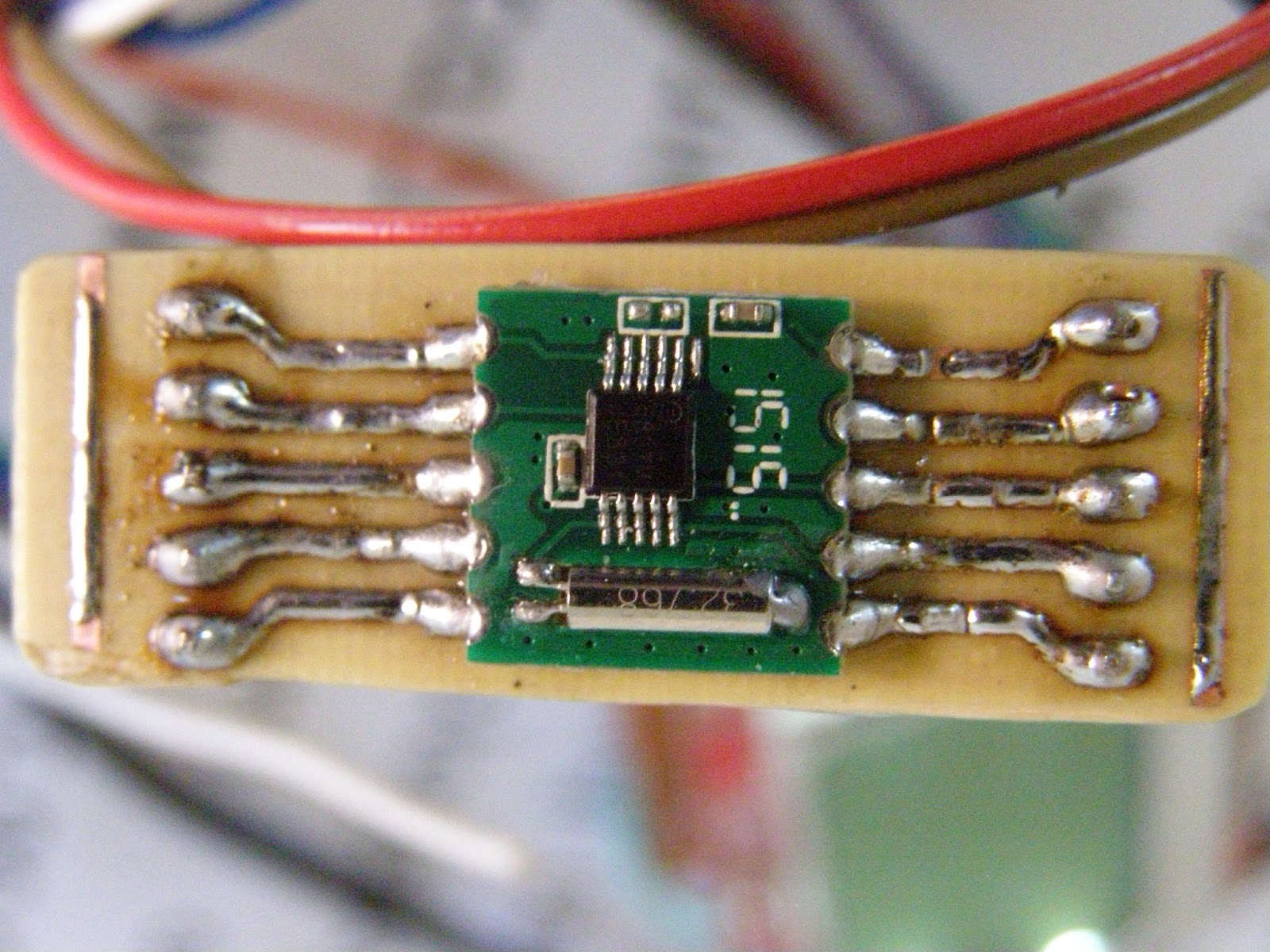
also I received the schematic for power the VFD:

Thursday, July 21, 2016

FM radio with RDA5807


   A FM radio with RDS info and digital volume can be made with RDA5807 module, who is similar as TEA5767 (pcb board & pins).
   For easy connexion, I made a adapter board from 2mm distance pins to 2.54mm:
   I found a russian article with fm radio who use RDA5807 chisp at http://full-chip.net/arduino-proekty/97-cifrovoy-fm-priemnik-na-arduino-i-module-rda5807-s-graficheskim-displeem-i-funkciey-rds.html
 
with this schematic:
   In this article is a movie named RDA5807 ФМ приемник на ARDUINO

  In russian sketch I found some words in spanish language and after few search I see article Arduino Radio RDA5807 con RDS LCD Nokia 3310
   I made some changes in sketch for optimal display of frequence value (my sketch is put on my Github channel - RDA5807_fmradio_3buttons_ver0.ino) for use with my configuration:
  I made few test without audio amplifier:
after that, I put PC speaker at radio module, see RDA5807 FM radio with RDS info on Nokia 5110 display using Arduino (3) movie:
   In I push MENU button, the cases are:
- AUTOMATIC SHEARCH:
- INFO:
- MANUAL SEARCH:
- VOLUME (16 steps, from 0 to 15):
   I made some changes in sketch and now frequency and step volume are stored in EEPROM memory, see RDA5807_fmradio_3buttons_ver1.ino, see results in next movie: RDA5807 FM radio with RDS info on Nokia 5110 display using Arduino (4)

Friday, July 8, 2016

MCP4261 as logarithmic potentiometer

   In previous article, I tested my MCP4261-502E/P dual digital potentiometer, now I show you how can use this dual potentiometer for audio (volume control), for that must change liniar characteristic to logarithmic characteristic (or like this).
   So, I use info from article Controlling Volume - log pots publish on TEXAS INSTRUMENS's site.
   
   For simple sketch and for not use more resource, I use log aproxximation, so I calculate the equations for each straights:
- for first, from 0 to 63%: y = x/5 (I know x=0 -> y=0 & x=50 -> y=10)
- for second, from 63 to 100%: y = 7/3 * x - 400/3 (I know x=70 y=30 & x=100 -> y=100)
  I use same schematic like in previous article:
and I write a sketch for test more cases, this sketch is MCP4261_lin_to_log_1.ino .
  I made 2 movies:

  For digital potentiometer with 16 steps + mute, I have next cases:
   Centralizing, we see some errors but for me there are acceptable:
and I cat continue experiments for implements this digital potentiometer in future audio project..