A few weeks ago, I posted article named "DCC ready" board for classical locomotive (DC loco) where it presented how can be use the "DCC ready" board
For add the NEM652 decoder on DCC ready board you must remove small 8-pin board and connect the decoder:
- initial
- remove 8-pin board
- add NEM652 decoder, with correct position
I found some info about the NEM652 decoder: In order to test the decoder I used info and files from https://dcc-ex.com/index.html. I used for tests:
- 0-30V/0-10A power supply (set to 12V voltage & 2A maximum current)
- Arduino Mega board (clone)
- Arduino Motor shield (clone)
- LCD1602 display + i2c interface (added later)
First I cut trace for VIN as in article from https://dcc-ex.com/get-started/assembly.html
- initial (using a DMM on diode domain, test if resistance is near 0Ω)
- after (using a DMM on diode domain, test if resistance is big, OL - open load on display)
I used easy way using installer for sketch in Arduino as in article from https://dcc-ex.com/get-started/installer.html
For controller (Throttle) I used a web throttle as in article from https://dcc-ex.com/get-started/controllers.htmlI used an Automatic white/red light for analog locomotive (DC) instead DC motor:
I make a video named test a DCC decoder (NEM652) with Arduino Web Throttle where I presented how I used the Web Throttle and how react board with NEM652 decoder.
Later, I added LCD1602display with i2c interface and I used again installer. Decimal address is 63 for 3F as hexa number for i2c interface adsress

On display of command station is shown logo
or state of decoder
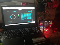
Adapter board + NEM652 decoder + bicolor led as "locomotive" and Arduino Mega + Motor Shield + display as command station:
- forward
- backward
20.04.2022
I want to find if my decoder has active Function 1 (pin 3) and Function 2 (free purple wire) so I added a green led at pin 3 in series with 3k3 resistor to pin 7 (common V+), also I added a yellow led at free purple wire in series with 3k3 resistor to pin 7 (common V+). Usual value for serie resistor is 1kΩ, but 3k3 was in my way.
I make another video, named test a DCC decoder (NEM652) with Arduino Web Throttle - 2, where you see how I control "digital locomotive" through Web Throttle Later, I added a wi-fi board with ESP8266-01 at Station:and I uploaded sketch in Arduino Mega using the installer:after I find channel for my wi-fi (bbk2 - channel 4):On display we see the IP adress and port for station: I install Engine Driver application on my Android phone (see more info about aplication in article Choosing a Controller (Throttle) I tested also Function 1 (Bell) and Function 2 (Horn)
22.04.2022
I tested the system with Android Throttle (Engine Driver application) and I make a video named test NEM decoder with DCC++EX Arduino Station and Android Throttle. For this situation, information on LCD display are very useful (IP and Port).


