Tuesday, September 22, 2015

GPRS module with M590 for SMS projects (part 3)

   In 1st part I present you few data about GPRS module with M590 chip and how send SMS from them. In 2rd part I send SMS from phone and SMS is received by GPRS module with M590, also with Arduino Mega board cand control 4 leds, depend text from SMS.
   M590 chip from Neoway is an old, industrial and... recovered (second hand) chip for GPRS/GPS as SIM900. Is enough for our tests with Arduino...
   Main reason for i use Arduino Mega board instead Arduino Uno is number of harware serial port... M590 chip has defauld speed set at 115200bps, too much for SerialSofware (see arduino.cc - SoftwareSerial). Theoretical, this library work fine at this speed but all my Arduino board (original and clone) not work good.
   So, my solution is to connect at Arduino Mega board and decrease speed with AT command: AT+IPR=9600. First upload M590_mega_serialtest2.ino and open serial monitor at 115200bps:
after that, I reopen serial monitor at 9600bps speed:
   Now, I chamge the schematic and use Arduino Uno board (in my case is a clone VISduinoUno):
and upload M590_softwareserial.ino and  send few AT commands:
   I  made a new schematic:
and upload M590_tronixstuff_4led_control.ver1m1.ino.
   I send SMS from phone for have all 4 leds lit (on):
 and GPRS with M590 module received SMS and Arduino decode and control leds:
    I send a new SMS:
after, I send a new SMS:
   I made few movie:
- SMS control 4 leds using M590 GPRS module and Arduino
- SMS control 4 leds using M590 GPRS module and Arduino (2)
- SMS control 4 leds using M590 GPRS module and Arduino (3)
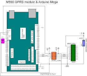
   If you haven't Arduino Mega, you can use USB-FTDI interface with 3.3V selector and made schematic:
 and use Putty software (like in 1st part) and change speed from 115200bps in 9600bps for work with Arduino Uno board (or clones).

 NOTE: External power supply is +4,6V not 4,2V (power supply with voltmeter show less with 0,3-0,4V) !

Monday, September 21, 2015

GPRS module with M590 for SMS projects (part 2)

   In previous article I present you a GPRS kit with M590 chip on-board and I send SMS when push an button. Now, I will received a SMS and interpret the text and comand few leds as in article named Tutorial – Arduino and SIM900 GSM Modules from tronixstuff.com.
   M590 chip is similar with SIM900, just haven't voice part... 
   First, I upload M590_Mega_serialmonitor.ino sketch and I send from phone a SMS to GPRS module:
   I use this schematic for tests:
   I upload M590_tronixstuff_sms_control_Arduino_v1m0.ino sketch and send #a1b0c1d0 text in SMS from phone:
(aprins = on, stins = off)
and leds 1 & 3 are on, 2 & 4 are off:
   I send #a0b1c0d1 SMS:
(aprins = on, stins = off)
and leds 1 & 3 are off, 2 & 4 are on:
   I send a new SMS, for all leds lit (all on):
and all led are lit.
   I made a movie named SMS control 4 leds using M590 GPRS module and Arduino with sending sms from phone and received from M590 GPRS module, interpret datas and comand 4 leds:

 NOTE: External power supply is +4,6V not 4,2V (power supply with voltmeter show less with 0,3-0,4V) !

GPRS module with M590 for SMS projects (part 1)

original article


   I buy a "DIY KIT GSM GPRS 900 1800 MHz Short Message Service SMS module for project for Arduino remote sensing alarm" based on M590 chip from Neoway.
   After, we solder the components, the montage must be:
   In my case, the montage and FTDI-USB interface are:
I made a "reverse engineering" of my montage:
and is clear, is a simplified base schematic, put directly wire instead logical interface between Arduino board (or FTDI-USB interface) to M590:

   For protect M590 chip, I powered M590 GPRS module with external 4.2V and put a logical interface 5V/3V between Arduino and M590 module kit.
   For easy link with interface or other modules, I connect pins 6 & 8 with 4, and now I have 3 pins for GND:
   I choose Arduino Mega board because have 4 hardware serial ports. For comunication with PC, I use classical Rx-Tx port and for M590 GPRS kit, I use Rx2-Tx2 (Serial2) port.
   Another reason is speed too much for software serial port and I noticed some errors.
   First stept, is put Mega_serialmonitor.ino sketch and discover and learn AT commands (I use M590 - AT Command Sets v3.0" documment).

   Thru serial monitor using Arduino, I can't send SMS ar begin of experiments and I try a PC sofware named Putty and I made a new schematic:
   I verify what com are the interface:
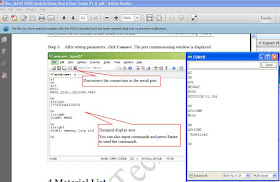
and made changes in Putty software configuration window:

   I write few AT commands on Putty window:
I on phone I received the SMS.
   I analyzed differents from Arduino style and Putty software and I realised in what sequence must be given commands to M590 GPRS module (I upload M590_Mega_sms_sender_v1m0.ino sketch)

and on my phone I see:
   Next step was to send a SMS from Arduino to phone when I push a button. I use M590_Mega_sms_sender_1button_ver1m0.ino sketch and this schematic:
   I made, also, 2 movie (in roumanian language):

 NOTE: External power supply is +4,6V not 4,2V (power supply with voltmeter show less with 0,3-0,4V) !

Monday, July 6, 2015

KTM-S1201: 12 Digit 7-segment LCD display

original article !!

   Like SDA5708: 8 character 7x5 dot matrix LED display, this display is received as gift for test.
   KTM-S1201 display is drived by NEC D7225 (UPD7225G) chip and I found a very usefull article named Arduino and KTM-S1201 LCD modules
   I use also info from www.pongrance.com
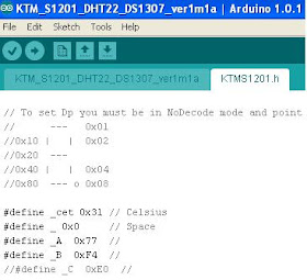
   For control this display with Arduino sketch must download KTMS1201.h file and put in same directory with sketch:
and in Arduino IDE software you see:
   First step was to made a pcb for schematic with a 10..20k variable resistor for contrast:
   Schematic is made after nest info:
   Test schematic is:
   After upload the example sketches and few changes in sketches, on display I can see:
   After that, I made a new schematic with DHT22 (AM2302) sensor:
   I write a sketch named KTMS1201_DHT22.ino and on display I can see:
   I finished the schematic with RTC clock module (made with DS3231, but work fine with DS1307) and KY-040 rotary encoder:
After upload KTMS1201_DHT22_RTC_ver1m0.ino sketch, I cand see:
- hour:
- humidity and temperature:
- data, after a short push:
- change mode, first year, after a long push (3-4 seconds):
- change month:
- change day:
- change hours:
- change minutes:
   I made few movie:
    Final sketch is KTMS1201_DHT22_RTC_ver1m1.ino and I use a changed KTMS1201.h file for C and Y letters:
   Finally, I change the sketch (see KTMS1201_DHT22_RTC_ver1m1b.ino) for another style for humidity: