Total Pageviews

Saturday, April 20, 2019

Delay off system using millis()

my original article

    In simple Arduino projects you can use delay command for have few seconds a led on and after that off, but in in this time program is halted. If you use millis() function, Arduino can execute other tests in program, not halt...
   In Arduino IDE program you cam find sketch named BlinkWithoutDelay
  In article Using millis() for timing you can find a good explanations
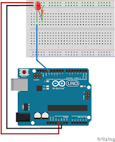
   I use this schematic for first test, using a push button and pull-up resistor on input
   If you upload delay_button.ino sketch, you will see next cases:
- standby state, led off:
- push buton, led off
- instantaneous, led on, time defined in sketch
- standby state, led off, again, waitting push button.
because I write the sketch using this chart
In Serial Monitor, you can see
   I change button with infrared module, schematic is
   For module sensor with normal state logic output (LOW in standby and HIGH when is triggered) sketch is delay_sensor.ino
and if you use other sensors with negative state logic output (HIGH in standby and LOW when is triggered) sketch is delay_sensor1.ino
    I made movie named delay off using millis()
    For this sketch(es), states are:
- stanfby, led off
- sensor is triggered, led is instant on
- led is on few seconds (selected in sketch), led is on
- after few seconds (selected in sketch), led is off
Also, in Serial Monitor, you can see the states:

Saturday, April 13, 2019

Simple alarm system with Arduino

original article
   A simple system alarm can be made with Arduino board, a sensor module (sound, PIR, Doppler, etc) and 2 switch or remote control.
   Base schematic is
If use buttons (switches) for control alarmsystem_0.ino is use without change
but is use remote control (singnal in HIGH) must changed in
Also, if sensor is like mine (infrared sensor) sketch is without change
but it easy to change in
for negative logic comand (active in LOW).
    After powered the system, alarm is in stand-by
and after push ON button (or button from remote control), alarm is in waitting mode
If sensor is activated, sound (yellow led in my case) is intermittently powered 10 second or more, depend value from here
   You can see 2 video:
20.04.2019
   I add a new movie with this alarm system using RCWL-0516 Doppler (radar) sensor (this sensor was tested a few time ago an posted at http://nicuflorica.blogspot.com/2018/02/senzor-de-miscare-tip-radar-doppler.html). 
   Default sketch is for power off the alarm system
but you can change to be armed after powered up dthe alarm system

Unidirectional Communcation between 2 Arduino boards

original article

   I want to send many commands using just 1 wire (and ground) so I use 2 Arduino boards.
   Base schematic for unidirectional communcication between Arduino boards is
and you can test this simple mode communication using info from article Tech Thurday #005: Arduino to Arduino Serial Communication.
   For sender (transmiter) I use a keypad with LCD1602 shield (see https://www.dfrobot.com/
This shield has the schematic
   Test schematic is
and sketch for transmiter is transmiter_v0.ino and sketch for receiver is receiver_v0.ino.
   If you have v.1.1 shield you must have
and for v.1.0
   I made Unidirectional Communication between 2 Arduino boards
  The states for this system are:
- all button are free (not pushed)
- if you push SELECT button
if you push LEFT button
if you push RIGHT button
if you push UP button
if you push DOWN button
 

Sunday, February 24, 2019

Measure times using millis()

   If you need to find the time what a button is pusshed or you want to use one button for made more function (short or long push / short, medium or long push) it can use millis() function with Arduino  language.
   Information for this thechnique (method) I found it on Doz's Blog.
   For test, I use a simple schematic (one button) and pushtime1button.ino program (sketch).
    For understand more ok the style of use, I tested also with 2 buttons, using pushtime2buttons.ino sketch.
     I made a short movie named measure times using millis() where is mase some tests:

Thursday, December 27, 2018

Animated adjusting clock with termomether and hygrometer on 7 segment led display

  After a discution with GeoMar, I decided to made a clock with few animation when change informations on 4 digit 7-segment led display.
   Last test was made be me with LFD080AAG-103 led display, who is with common anode:
    Base schematic is used in some projects
but I put control for brightness (automatic or manual)
or 
and 2 buttons for adjust clock and data
    Sketch multiplexed_scroll_clock3.ino made a clock who has next informations:
- clock, with flash led for beat seconds, about 10 seconds
- temperature, about 2,5 seconds
- relavive humidity for air, about 2,5 seconds
- data (day and mounts), about 2,5 secods
   Brightness can be control in 1024 steps when it used photoresistor or in 2 (minumum or maximum) wirh switch
   If is pushed MENU button, clock enter in adjusting mode, first for hour, so, you will see hour flashing and can be increase value by pushing + button, but if hour is 23 and + button is pushed, value for hour is 00...
   If is pushed again MENU button, clock enter in adjusting mode for minutes, so, you will see minutes flashing and can be increase value by pushing + button, but if minutes are 59 and + button is pushed, value for minutes are 00...
   Next push of MENU button go to year changes, from 2018 to 2049
After that, if push again MENU button, you can change month (1 to 12)
and if push again on MENu button you can change day of month (just day flash)
After a new push of MENU button, system enter in clock mode (normal mode).
    I made a movie for see how clock show the datas and how can be changes clock and data:

Note: Schematic work for small led display with common anode
or common cathode
   Base schematic is similar
   If you want to see in night just clock and temperature, when is day all informations (clock, temperature, relative humidity and data) you must upload sketch multiplexed_scroll_clock3a.ino !