Total Pageviews

Friday, September 26, 2014

Manual adjust for RTC clock with Arduino and 7-segment LED display

   For a good clock must use a RTC (real-time clock) like DS1307. For Arduino enthusiasts and hobbylist exists some RTC module with DS1307, but you can made yourself a good RTC module like me.
   Original schematic is from DS1307 datasheet, but I redesigned schematic using freeversion of Eagle PCB Software:
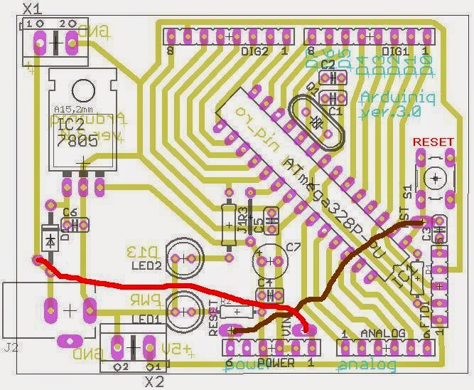
   Note: Battery is CR2032, like in schematic... in boards is a little error

   A full schematic for RTC clock with Arduino is:

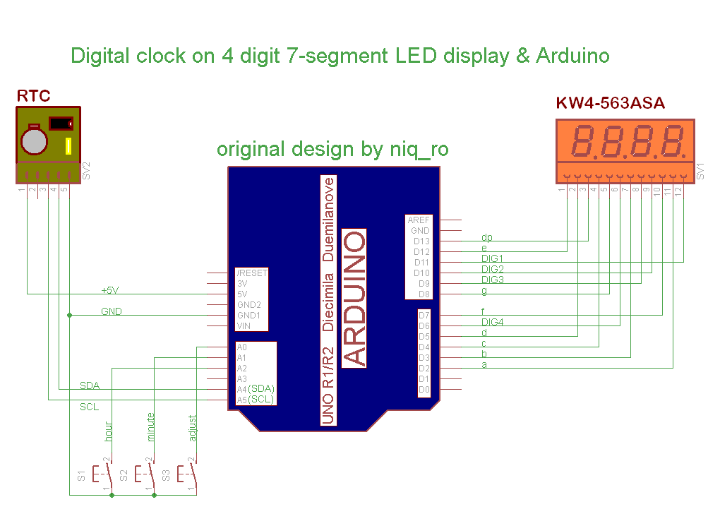
   Compared to other schematics that can adjust time (reset clock at 0:00, adjust hours and minutes). Original schematic, design and sketch is from article Using Arduino with a DS1307 Real Time Clock by Lewis Loflin.
   If you want to change time, must push and hold S3 (adjust) switch and display is change on 0:00, then push S1 (hour) or S2 (minute) repeatedly until time is ok, after this realise S3, and time is put in RTC.
   I use a multiplexed 4-digit 7-segment display with common anode same in article named Arduino UNO running 4-digit 7-segment display from http://www.hobbytronics.co.uk/. Is a unusual schematic, but works fine; a usual schematic use resistors for current limit.
   My sketch is:
/*
 4 digit 7 segment display: http://www.sparkfun.com/products/9483
 Datasheet: http://www.sparkfun.com/datasheets/Components/LED/7-Segment/YSD-439AR6B-35.pdf
 7 segments + 4 digits + 1 colon = 12 pins required for full control 
 */
// modified connexion by niq_ro from http://nicuflorica.blogspot.com
// for my Luckylight KW4-563ASA
// dataseet: http://www.tme.eu/ro/Document/dfc2efde2e22005fd28615e298ea2655/KW4-563XSA.pdf

int digit1 = 11; //PWM Display pin 12 (digit1 is common anonds A1 from right side)
int digit2 = 10; //PWM Display pin 9 (digit2 is  common A2)
int digit3 = 9; //PWM Display pin 8 (digit3 is common anods A3)
int digit4 = 6; //PWM Display pin 6 (digit4 is common anods, from left side)

//Pin mapping from Arduino to the ATmega DIP28 if you need it
//http://www.arduino.cc/en/Hacking/PinMapping
int segA = 2; //Display pin 11
int segB = 3; //Display pin 7
int segC = 4; //Display pin 4
int segD = 5; //Display pin 2
int segE = 12; //Display pin 1
int segF = 7; //Display pin 10
int segG = 8; //Display pin 5
int segDP = 13; // Display pin 3

#include <Wire.h>
#include "RTClib.h"
RTC_DS1307 RTC;

// Date and time functions using a DS1307 RTC connected via I2C and Wire lib
// original sketck from http://learn.adafruit.com/ds1307-real-time-clock-breakout-board-kit/
// add part with SQW=1Hz from http://tronixstuff.wordpress.com/2010/10/20/tutorial-arduino-and-the-i2c-bus/
// add part with manual adjust http://www.bristolwatch.com/arduino/arduino_ds1307.htm

byte SW0 = A0; byte SW1 = A1; byte SW2 = A2; // use for hexa in zecimal conversion int zh, uh, ore; int zm, um, miniti; void setup() {     // Serial.begin(57600);   Wire.begin();   RTC.begin(); // RTC.adjust(DateTime(__DATE__, __TIME__)); // if you need set clock... just remove // from line above this // part code for flashing LED Wire.beginTransmission(0x68); Wire.write(0x07); // move pointer to SQW address // Wire.write(0x00); // turns the SQW pin off  Wire.write(0x10); // sends 0x10 (hex) 00010000 (binary) to control register - turns on square wave at 1Hz // Wire.write(0x13); // sends 0x13 (hex) 00010011 (binary) 32kHz Wire.endTransmission();   if (! RTC.isrunning()) {     Serial.println("RTC is NOT running!");     // following line sets the RTC to the date & time this sketch was compiled     RTC.adjust(DateTime(__DATE__, __TIME__));   }       // dht.begin();   pinMode(segA, OUTPUT);   pinMode(segB, OUTPUT);   pinMode(segC, OUTPUT);   pinMode(segD, OUTPUT);   pinMode(segE, OUTPUT);   pinMode(segF, OUTPUT);   pinMode(segG, OUTPUT);   pinMode(segDP, OUTPUT);   pinMode(digit1, OUTPUT);   pinMode(digit2, OUTPUT);   pinMode(digit3, OUTPUT);   pinMode(digit4, OUTPUT);    //  pinMode(13, OUTPUT);  Serial.begin(9600);  Serial.println("test for niq_ro");  pinMode(SW0, INPUT); // for this use a slide switch   pinMode(SW1, INPUT); // N.O. push button switch   pinMode(SW2, INPUT); // N.O. push button switch   digitalWrite(SW0, HIGH); // pull-ups on   digitalWrite(SW1, HIGH);   digitalWrite(SW2, HIGH); } void loop() { digitalWrite(segDP, HIGH);   DateTime now = RTC.now();   int timp = now.hour()*100+now.minute(); //   int timp = (now.minute(), DEC); //   displayNumber(12); // this is number to diplay //   int timp = 1234;   Serial.print(now.hour(), DEC);   Serial.print(":");   Serial.print(now.minute(), DEC);   Serial.print(" -> ");   Serial.print(timp);   Serial.println(" !"); // display parts       for(int i = 250 ; i >0 ; i--) {      if (timp >= 1000) displayNumber01(timp);      else displayNumber02(timp);    }     for(int i = 250 ; i >0 ; i--) {      if (timp >= 1000) displayNumber03(timp);      else displayNumber04(timp);    }    if (!(digitalRead(SW0))) set_time(); // hold the switch to set timevoid set_time() {   byte minutes1 = 0;   byte hours1 = 0;   byte minutes = 0;   byte hours = 0;   while (!digitalRead(SW0)) // set time switch must be released to exit   {     minutes1=minutes;     hours1=hours;                while (!digitalRead(SW1)) // set minutes     {       minutes++;      // converting hexa in zecimal:     zh = hours / 16;     uh = hours - 16 * zh ;     ore = 10 * zh + uh;      zm = minutes / 16;     um = minutes - 16 * zm ;     miniti = 10 * zm + um;            for(int i = 20 ; i >0 ; i--) {      displayNumber01(ore*100+miniti);       }              if ((minutes & 0x0f) > 9) minutes = minutes + 6;       if (minutes > 0x59) minutes = 0;       Serial.print("Minutes = ");       if (minutes >= 9) Serial.print("0");       Serial.println(minutes, HEX);     delay(150);     }     while (!digitalRead(SW2)) // set hours     {       hours++;                    // converting hexa in zecimal:     zh = hours / 16;     uh = hours - 16 * zh ;     ore = 10 * zh + uh;      zm = minutes / 16;     um = minutes - 16 * zm ;     miniti = 10 * zm + um;            for(int i = 20 ; i >0 ; i--) {      displayNumber01(ore*100+miniti);       }                  if ((hours & 0x0f) > 9) hours = hours + 6;       if (hours > 0x23) hours = 0;       Serial.print("Hours = ");       if (hours <= 9) Serial.print("0");       Serial.println(hours, HEX);     delay(150);     }     Wire.beginTransmission(0x68); // activate DS1307     Wire.write(0); // where to begin     Wire.write(0x00); //seconds     Wire.write(minutes); //minutes     Wire.write(0x80 | hours); //hours (24hr time)     Wire.write(0x06); // Day 01-07     Wire.write(0x01); // Date 0-31     Wire.write(0x05); // month 0-12     Wire.write(0x09); // Year 00-99     Wire.write(0x10); // Control 0x10 produces a 1 HZ square wave on pin 7.     Wire.endTransmission();        // converting hexa in zecimal:     zh = hours / 16;     uh = hours - 16 * zh ;     ore = 10 * zh + uh;      zm = minutes / 16;     um = minutes - 16 * zm ;     miniti = 10 * zm + um;            for(int i = 20 ; i >0 ; i--) {      displayNumber01(ore*100+miniti);       }  // delay(150);        }    } void displayNumber01(int toDisplay) { #define DISPLAY_BRIGHTNESS  500 #define DIGIT_ON  HIGH #define DIGIT_OFF  LOW   for(int digit = 4 ; digit > 0 ; digit--) {     //Turn on a digit for a short amount of time     switch(digit) {     case 1:      digitalWrite(digit1, DIGIT_ON);      digitalWrite(segDP, HIGH);       break;    case 2:       digitalWrite(digit2, DIGIT_ON);       digitalWrite(segDP, LOW);       break;     case 3:       digitalWrite(digit3, DIGIT_ON);       digitalWrite(segDP, HIGH);       break;     case 4:       digitalWrite(digit4, DIGIT_ON);       digitalWrite(segDP, HIGH);       break;     }     lightNumber(toDisplay % 10);     toDisplay /= 10;     delayMicroseconds(DISPLAY_BRIGHTNESS);      //Turn off all segments     lightNumber(10);      //Turn off all digits     digitalWrite(digit1, DIGIT_OFF);     digitalWrite(digit2, DIGIT_OFF);     digitalWrite(digit3, DIGIT_OFF);     digitalWrite(digit4, DIGIT_OFF); } }  void displayNumber02(int toDisplay) { #define DISPLAY_BRIGHTNESS  500 #define DIGIT_ON  HIGH #define DIGIT_OFF  LOW   for(int digit = 4 ; digit > 0 ; digit--) {     //Turn on a digit for a short amount of time     switch(digit) {     case 1:      lightNumber(10);       digitalWrite(segDP, HIGH);      break;    case 2:       digitalWrite(digit2, DIGIT_ON);       digitalWrite(segDP, LOW);       break;     case 3:       digitalWrite(digit3, DIGIT_ON);       digitalWrite(segDP, HIGH);       break;     case 4:       digitalWrite(digit4, DIGIT_ON);       digitalWrite(segDP, HIGH);       break;     }     lightNumber(toDisplay % 10);     toDisplay /= 10;     delayMicroseconds(DISPLAY_BRIGHTNESS);      //Turn off all segments     lightNumber(10);      //Turn off all digits     digitalWrite(digit1, DIGIT_OFF);     digitalWrite(digit2, DIGIT_OFF);     digitalWrite(digit3, DIGIT_OFF);     digitalWrite(digit4, DIGIT_OFF); } }  void displayNumber03(int toDisplay) { #define DISPLAY_BRIGHTNESS  500 #define DIGIT_ON  HIGH #define DIGIT_OFF  LOW   for(int digit = 4 ; digit > 0 ; digit--) {     //Turn on a digit for a short amount of time     switch(digit) {     case 1:      digitalWrite(digit1, DIGIT_ON);      digitalWrite(segDP, HIGH);       break;    case 2:       digitalWrite(digit2, DIGIT_ON);       digitalWrite(segDP, HIGH);       break;     case 3:       digitalWrite(digit3, DIGIT_ON);       digitalWrite(segDP, HIGH);       break;     case 4:       digitalWrite(digit4, DIGIT_ON);       digitalWrite(segDP, HIGH);       break;     }     lightNumber(toDisplay % 10);     toDisplay /= 10;     delayMicroseconds(DISPLAY_BRIGHTNESS);      //Turn off all segments     lightNumber(10);      //Turn off all digits     digitalWrite(digit1, DIGIT_OFF);     digitalWrite(digit2, DIGIT_OFF);     digitalWrite(digit3, DIGIT_OFF);     digitalWrite(digit4, DIGIT_OFF); } }  void displayNumber04(int toDisplay) { #define DISPLAY_BRIGHTNESS  500 #define DIGIT_ON  HIGH #define DIGIT_OFF  LOW   for(int digit = 4 ; digit > 0 ; digit--) {     //Turn on a digit for a short amount of time     switch(digit) {     case 1:      lightNumber(10);       digitalWrite(segDP, HIGH);      break;    case 2:       digitalWrite(digit2, DIGIT_ON);       digitalWrite(segDP, HIGH);       break;     case 3:       digitalWrite(digit3, DIGIT_ON);       digitalWrite(segDP, HIGH);       break;     case 4:       digitalWrite(digit4, DIGIT_ON);       digitalWrite(segDP, HIGH);       break;     }     lightNumber(toDisplay % 10);     toDisplay /= 10;     delayMicroseconds(DISPLAY_BRIGHTNESS);      //Turn off all segments     lightNumber(10);      //Turn off all digits     digitalWrite(digit1, DIGIT_OFF);     digitalWrite(digit2, DIGIT_OFF);     digitalWrite(digit3, DIGIT_OFF);     digitalWrite(digit4, DIGIT_OFF); } }  //Given a number, turns on those segments //If number == 10, then turn off number void lightNumber(int numberToDisplay) { #define SEGMENT_ON  LOW #define SEGMENT_OFF HIGH   switch (numberToDisplay){   case 0:     digitalWrite(segA, SEGMENT_ON);     digitalWrite(segB, SEGMENT_ON);     digitalWrite(segC, SEGMENT_ON);     digitalWrite(segD, SEGMENT_ON);     digitalWrite(segE, SEGMENT_ON);     digitalWrite(segF, SEGMENT_ON);     digitalWrite(segG, SEGMENT_OFF);     break;   case 1:     digitalWrite(segA, SEGMENT_OFF);     digitalWrite(segB, SEGMENT_ON);     digitalWrite(segC, SEGMENT_ON);     digitalWrite(segD, SEGMENT_OFF);     digitalWrite(segE, SEGMENT_OFF);     digitalWrite(segF, SEGMENT_OFF);     digitalWrite(segG, SEGMENT_OFF);     break;   case 2:     digitalWrite(segA, SEGMENT_ON);     digitalWrite(segB, SEGMENT_ON);     digitalWrite(segC, SEGMENT_OFF);     digitalWrite(segD, SEGMENT_ON);     digitalWrite(segE, SEGMENT_ON);     digitalWrite(segF, SEGMENT_OFF);     digitalWrite(segG, SEGMENT_ON);     break;   case 3:     digitalWrite(segA, SEGMENT_ON);     digitalWrite(segB, SEGMENT_ON);     digitalWrite(segC, SEGMENT_ON);     digitalWrite(segD, SEGMENT_ON);     digitalWrite(segE, SEGMENT_OFF);     digitalWrite(segF, SEGMENT_OFF);     digitalWrite(segG, SEGMENT_ON);     break;   case 4:     digitalWrite(segA, SEGMENT_OFF);     digitalWrite(segB, SEGMENT_ON);     digitalWrite(segC, SEGMENT_ON);     digitalWrite(segD, SEGMENT_OFF);     digitalWrite(segE, SEGMENT_OFF);     digitalWrite(segF, SEGMENT_ON);     digitalWrite(segG, SEGMENT_ON);     break;   case 5:     digitalWrite(segA, SEGMENT_ON);     digitalWrite(segB, SEGMENT_OFF);     digitalWrite(segC, SEGMENT_ON);     digitalWrite(segD, SEGMENT_ON);     digitalWrite(segE, SEGMENT_OFF);     digitalWrite(segF, SEGMENT_ON);     digitalWrite(segG, SEGMENT_ON);     break;   case 6:     digitalWrite(segA, SEGMENT_ON);     digitalWrite(segB, SEGMENT_OFF);     digitalWrite(segC, SEGMENT_ON);     digitalWrite(segD, SEGMENT_ON);     digitalWrite(segE, SEGMENT_ON);     digitalWrite(segF, SEGMENT_ON);     digitalWrite(segG, SEGMENT_ON);     break;   case 7:     digitalWrite(segA, SEGMENT_ON);     digitalWrite(segB, SEGMENT_ON);     digitalWrite(segC, SEGMENT_ON);     digitalWrite(segD, SEGMENT_OFF);     digitalWrite(segE, SEGMENT_OFF);     digitalWrite(segF, SEGMENT_OFF);     digitalWrite(segG, SEGMENT_OFF);     break;   case 8:     digitalWrite(segA, SEGMENT_ON);     digitalWrite(segB, SEGMENT_ON);     digitalWrite(segC, SEGMENT_ON);     digitalWrite(segD, SEGMENT_ON);     digitalWrite(segE, SEGMENT_ON);     digitalWrite(segF, SEGMENT_ON);     digitalWrite(segG, SEGMENT_ON);     break;   case 9:     digitalWrite(segA, SEGMENT_ON);     digitalWrite(segB, SEGMENT_ON);     digitalWrite(segC, SEGMENT_ON);     digitalWrite(segD, SEGMENT_ON);     digitalWrite(segE, SEGMENT_OFF);     digitalWrite(segF, SEGMENT_ON);     digitalWrite(segG, SEGMENT_ON);     break;   // all segment are ON   case 10:     digitalWrite(segA, SEGMENT_OFF);     digitalWrite(segB, SEGMENT_OFF);     digitalWrite(segC, SEGMENT_OFF);     digitalWrite(segD, SEGMENT_OFF);     digitalWrite(segE, SEGMENT_OFF);     digitalWrite(segF, SEGMENT_OFF);     digitalWrite(segG, SEGMENT_OFF);     break;      } }
Note: Original article in roumanian language is Afisaje LED cu 7 segmente si.. Arduino (IV)!!!

11.10.2016
   I correct sketch for display 10:00 case..
07.02.2017
    Now, I pun on my Github channel sketch for cathode comon display, see github.com/tehniq3/multiplexedclock

Tuesday, September 23, 2014

Arduino Due and 2.2" TFT display with ILI9341 driver

   I recently purchased an Arduino Due development board to control 2.2" TFT color graphic display with ILI9341 driver.
   First, I use Arduino Uno then I use Arduino Mega for control this display. Between Arduino board (Uno or Mega) I use CD4050 for convert voltage level, because Uno and mega works with 5V logical level and display with ILI9341 driver works with 3.3V.
   After several attempts I chose ucglib library because is like u8glb library, that I used it at monochrome Nokia mobile displays (like Nokia 3310 display with 84x48 resolution using PCD8544 driver or Nokia 3410 display with 95x64 resolution using PCF8812 driver 3410) or at monochrome display with 128x64 resolution using ST7920 driver.
   I tested with very good results the ucglib library with Arduino Uno & Due for control the colour graphic display with 320x240 resolution using ILI9341 driver and I write few article in roumanian language, who is my native language.
   Also, I write an article in roumanian language with Arduino Due who control the colour graphic display with 320x240 resolution using ILI9341 driver: Arduino Due si afisajul QVGA de 2,2" (5,6cm) comandat de ILI9341.
   Now, I make a summary of that article for interested people...
   Arduino Due is more powerfull then other Arduino boards, becouse runs at 3.3V (maximum tolerate voltage at input or output pins is 3.3V).
   Using informations from article named How to Connect a ILI9341 Display I connect directly pins from Arduino Due and display, like in this picture:
   In my case, schematic is:
   First, I made a weather station with DTH11 sensor for humidity and BMP180 for pressure and temperature, schematic is:
   Then, I simplified the sketch for using just DHT11 sensor for humidity and temperature:
   Practical, wirred is:
   My original sketck for full weather station with BMP180 and DHT11 is:
/*
original sketch by niq_ro from http://nicuflorica.blogspot.com using ucglib library
version for 2.2" TFT with ILI9341  - 2014.07.29, Craiova - Romania
use Universal uC Color Graphics Library from https://code.google.com/p/ucglib/
*/
#include <SPI.h>
#include "Ucglib.h"
//Ucglib_ILI9341_18x240x320_HWSPI ucg(/*cd=*/ 6 , /*cs=*/ 5, /*reset=*/ 4); // at Uno
//Ucglib_ILI9341_18x240x320_HWSPI ucg(/*cd=*/ 26 , /*cs=*/ 24, /*reset=*/ 22); // at Mega
//Ucglib_ILI9341_18x240x320_SWSPI ucg(/*sclk=*/ 52, /*data=*/ 51, /*cd=*/ 26 , /*cs=*/ 24, /*reset=*/ 22); //at Mega
//Ucglib_ILI9341_18x240x320_SWSPI ucg(/*sclk=*/ 76, /*data=*/ 75, /*cd=*/ 26 , /*cs=*/ 24, /*reset=*/ 22); //at Mega
Ucglib_ILI9341_18x240x320_HWSPI ucg(/*cd=*/ 26 , /*cs=*/ 24, /*reset=*/ 22); //at Mega and Due
/*

Due  |Mega | Uno | TFT - ILI9341
----------------------
D22  | D22 | D4  | RESET
D24  | D24 | D5  | CS
D26  | D26 | D6  | D/C
 ?   | ?   | LED (via 220 ohms resistor at 5V)
MOSI | D51 | D11 | MOSI
MISO | D50 | D12 | MISO
SCK  | D52 | D13 | SCK
-----------------------------
with CD4050 adapter or 10k resistor, power supply and logical levels is 3.3V
schematic: http://nicuflorica.blogspot.ro/2014/07/afisaj-grafic-color-qvga-de-22-cu.html
*/

#include <dht.h> 
// from http://playground.arduino.cc/Main/DHTLib
dht DHT;

float t1, t2;
float t10, t20;
float t11, t21;
float t12, t22;
float t13, t23;
int h11, h12;

void setup() {
delay(1000);

ucg.begin(UCG_FONT_MODE_TRANSPARENT);
ucg.clearScreen();
ucg.setFont(ucg_font_ncenR14r);
ucg.setColor(255, 0, 255);
ucg.setColor(1, 255, 0,0);

  ucg.setRotate90();
  ucg.setColor(255, 255, 255); // culoare alba
  ucg.drawFrame(0,0,320,240); //   
  ucg.setFont(ucg_font_courB24); // 20 pixel height
  ucg.setColor(255, 0, 0); // culoare rosie
  ucg.setPrintPos(60,30);
  ucg.print("Ministatie");
  ucg.setColor(0, 255, 0); // culoare verde
  ucg.setColor(0, 255, 0);
  ucg.setColor(0, 0, 255); // culoare albastru
  ucg.setPrintPos(17, 60);
  ucg.print("meteo cu DHT11");
//  ucg.setPrintPos(55, 90);
//  ucg.setColor(5, 255, 0); // culoare verde
//  ucg.print("si BMP180");
  ucg.setFont(ucg_font_fur17r); // 17 pixel height
  ucg.setColor(255, 255, 0); // culoare galbena
  ucg.setPrintPos(25,120);
  ucg.print("ecran grafic 2,2'' (5,6cm)");
  ucg.setFont(ucg_font_courB24); // 20 pixel height 
  ucg.setColor(0, 255, 255); // culoare bleo
  ucg.setPrintPos(10,150);
  ucg.print("QVGA cu ILI9341");
  ucg.setColor(255, 0, 255); // culoare mov
  ucg.setPrintPos(20,180);
  ucg.print("versiune 4.5.0");
  ucg.setFont(ucg_font_fur17r); // 17 pixel height
  ucg.setColor(255, 255, 255); // culoare alb
  ucg.setPrintPos(60,210);
  ucg.print("realizare niq_ro");

delay(5000);
ucg.clearScreen();
t13=40.0;
h12=40.0;
}

void loop() {
     
 // DHT11 part
 int chk = DHT.read11(37);
 delay(1000);
// timeout;
 int h11 = DHT.humidity; 
 if (DHT.humidity < 0) h11 = 0;

 int t12 = DHT.temperature;
int t15 = t12;
float t16 = 10*t15;
t16 = t16/10;

t16 = t12;
if (t16 != t13) 
{
temperaturi(t16, t13, 20, 0); // temperature, old temperature, x,y
termometre(t16, 20);
}

if (h11 != h12) 
{
// umiditate(h11, h12, 115, 90); // humidity, old humidity, x, y
 umiditate(h11, h12, 40, 180); // humidity, old humidity, x, y
 barca (h11, h12);
}


//}
delay (30000); 
t13=t16;
h12=h11;
} // final de program, se revine de la inceput

void temperaturi(float t3, float t4, int ics, int igrec)
{
int t5 = t3;
int t6 = t4;
ucg.setFont(ucg_font_courB24);    
if (t3*t4 < 0)
{ucg.setColor(0, 0, 0); 
for (int qy = 39 ; qy < 60; qy++) 
{
 ucg.drawHLine(ics+7, qy + igrec , 105);
}
}
int t51 = t5/10;
int t61 = t6/10;
ucg.setColor(0, 0, 0); 
if (t51 != t61)
{
for (int qy = 39 ; qy < 60; qy++) 
{
ucg.drawHLine(ics+28, qy + igrec , 21);
}
}
t5 = t3 - t51*10;
t6 = t4 - t61*10;
if (t5 != t6)
{
for (int qy = 39 ; qy < 60; qy++) 
{
ucg.drawHLine(ics+49, qy + igrec , 21);
}
} 
for (int qy = 39 ; qy < 60; qy++) 
{
 ucg.drawHLine(ics+91, qy + igrec , 21);
}
ucg.setColor(255, 0, 0);  
ucg.setPrintPos(10 + ics, 30 + igrec);
//ucg.print("t  :"); 
ucg.print("temperatura:"); 
ucg.setPrintPos(10 + ics, 60 + igrec);
if (t3 > 10.0) ucg.print("+");
else
 if (t3>0.0) ucg.print(" +");
else
 if (t3<0.0)
{
 t3=-t3;
 if (t3 > 10.0) ucg.print("-");
else
 if (t3 > 0.0) ucg.print(" -");
}  
if (t3==0.0) ucg.print("  ");
ucg.print(t3,1); 
ucg.print(" C"); 
ucg.setFont(ucg_font_fur17r); 
ucg.setPrintPos(30 + ics, 35 + igrec);
//if (igrec == 0) ucg.print("int"); 
//else ucg.print("ext"); 
ucg.setPrintPos(115 + ics, 50 + igrec);
ucg.print("o"); 

ucg.setPrintPos(75 + ics, 60 + igrec);
ucg.print(",");


}

void termometre (float t, int ics1)
{
ucg.setColor(255, 255, 255);  
ucg.drawFrame(ics1-4,10,9,200); 
ucg.drawCircle(ics1,220,10,UCG_DRAW_ALL);  
for (int a = 0; a < 10; a++)
{
ucg.drawLine(ics1-5,20+20*a,ics1-7,20+20*a);
ucg.drawLine(ics1+5,20+20*a,ics1+7,20+20*a);
}
ucg.drawLine(ics1-10,140,ics1+10,140);  
ucg.setFont(ucg_font_courB24);    
ucg.setPrintPos(13 + ics1, 149);
ucg.print("0 C"); 
ucg.setFont(ucg_font_fur17r); 
ucg.setPrintPos(37 + ics1, 135);
ucg.print("o"); 
int lin = 140 - 2*t;
ucg.setColor(0, 0, 0);  // black 
ucg.drawBox(ics1-2,21, 5, lin+5);
ucg.setColor(255, 0, 0);  
ucg.drawDisc(ics1,220,8,UCG_DRAW_ALL);  
ucg.drawBox(ics1-2,lin, 5, 210-lin);
}

void umiditate(int h3, int h4, int zet, int igrec1)
{
  ucg.setFont(ucg_font_courB24); // 20 pixel height   

// sterg semnul ??
int h51 = h3/10;
int h61 = h4/10;

ucg.setColor(0, 0, 0); 

// sterg zeci daca e cazul
if (h51 != h61)
{
//ucg.setColor(255, 255, 0); 
ucg.setColor(0, 0, 0); 
for (int qy = 39 ; qy < 60; qy++) 
{
//  ucg.drawHLine(zet+28, qy + igrec1 , 21);
  ucg.drawHLine(zet+40, qy + igrec1, 42);
}
}
  int h5 = h3 - h51*10;
  int h6 = h4 - h61*10;

// sterg unitati daca e cazul
//if ((t5 != t6) || (t5-t6>0.2))
if (h5 != h6)
{
//ucg.setColor(0, 255, 0); 
ucg.setColor(0, 0, 0); 
for (int qy = 39 ; qy < 60; qy++) 
{
  ucg.drawHLine(zet+79, qy + igrec1 , 21);
}
} 

 ucg.setColor(0, 255, 255);  
 ucg.setPrintPos(zet, 30 + igrec1);
 ucg.print("umiditate:"); 


//ucg.setFont(ucg_font_fub42n); // 20 pixel height   
ucg.setPrintPos(40 + zet, 60 + igrec1);
//if (h3 > 10) ucg.print("+");
if (h3 > 10) ucg.print(" ");
else
{
//ucg.setColor(255, 255, 255); 
ucg.setColor(0, 0, 0); 
for (int qy = 39 ; qy < 60; qy++) 
{
  ucg.drawHLine(zet+40, qy + igrec1 , 42);
}
if (igrec1 <30) ucg.setColor(255, 255, 0);  
else ucg.setColor(0, 255, 255); 
ucg.setPrintPos(61 + zet, 60 + igrec1);
//ucg.print("+");
ucg.print(" ");
}
 ucg.print(h3); 
 ucg.print("%"); 
}


void barca (int h, int h2) // new humidity, old humidity.,
{
int xx = 280; 
int yy = 230;

//sterg barca
//ucg.setColor(100,100,100);  
ucg.setColor(0,0,0);  
ucg.drawBox(xx-25, yy-20-h2, 50, 30);


//sterg apa
//ucg.setColor(125, 125, 125);  
ucg.setColor(0, 0, 0);  
ucg.drawBox(xx-35, yy+10-h2, 70, h2-h);

//desenez apa
ucg.setColor(0, 255, 255);  
ucg.drawBox(xx-35, yy+10-h, 70, h);

//desenz barcuta;
//desenez carena
ucg.setColor(255, 255, 0);  
ucg.drawBox(xx-20, yy-h, 40, 10);
ucg.drawTriangle(xx-25, yy-h, xx-20, yy-h, xx-20, yy+10-h);
ucg.drawTriangle(xx+25, yy-h, xx+20, yy-h, xx+20, yy+10-h);
//desenez catarg
ucg.drawBox(xx-1, yy-20-h, 2, 20);
//desenez velele
ucg.setColor(0, 0, 255); // vela albastra  
ucg.drawTriangle(xx+2, yy-20-h, xx+2, yy-h, xx+20, yy-h);
ucg.setColor(255, 0, 0); // vela rosie  
ucg.drawTriangle(xx-2, yy-15-h, xx-2, yy-h, xx-20, yy-h);
}
/
   Sketch for simplified weather station just DHT11 is: 
/*
original sketch by niq_ro from http://nicuflorica.blogspot.com using ucglib library
version for 2.2" TFT with ILI9341  - 2014.07.29, Craiova - Romania
use Universal uC Color Graphics Library from https://code.google.com/p/ucglib/
*/
#include <SPI.h>
#include "Ucglib.h"
//Ucglib_ILI9341_18x240x320_HWSPI ucg(/*cd=*/ 6 , /*cs=*/ 5, /*reset=*/ 4); // at Uno
//Ucglib_ILI9341_18x240x320_HWSPI ucg(/*cd=*/ 26 , /*cs=*/ 24, /*reset=*/ 22); // at Mega
//Ucglib_ILI9341_18x240x320_SWSPI ucg(/*sclk=*/ 52, /*data=*/ 51, /*cd=*/ 26 , /*cs=*/ 24, /*reset=*/ 22); //at Mega
//Ucglib_ILI9341_18x240x320_SWSPI ucg(/*sclk=*/ 76, /*data=*/ 75, /*cd=*/ 26 , /*cs=*/ 24, /*reset=*/ 22); //at Mega
Ucglib_ILI9341_18x240x320_HWSPI ucg(/*cd=*/ 26 , /*cs=*/ 24, /*reset=*/ 22); //at Mega and Due
/*

Due  |Mega | Uno | TFT - ILI9341
----------------------
D22  | D22 | D4  | RESET
D24  | D24 | D5  | CS
D26  | D26 | D6  | D/C
 ?   | ?   | LED (via 220 ohms resistor at 5V)
MOSI | D51 | D11 | MOSI
MISO | D50 | D12 | MISO
SCK  | D52 | D13 | SCK
-----------------------------
with CD4050 adapter or 10k resistor, power supply and logical levels is 3.3V
schematic: http://nicuflorica.blogspot.ro/2014/07/afisaj-grafic-color-qvga-de-22-cu.html
*/

#include <dht.h> 
// from http://playground.arduino.cc/Main/DHTLib
dht DHT;

float t1, t2;
float t10, t20;
float t11, t21;
float t12, t22;
float t13, t23;
int h11, h12;

void setup() {
delay(1000);

ucg.begin(UCG_FONT_MODE_TRANSPARENT);
ucg.clearScreen();
ucg.setFont(ucg_font_ncenR14r);
ucg.setColor(255, 0, 255);
ucg.setColor(1, 255, 0,0);

  ucg.setRotate90();
  ucg.setColor(255, 255, 255); // culoare alba
  ucg.drawFrame(0,0,320,240); //   
  ucg.setFont(ucg_font_courB24); // 20 pixel height
  ucg.setColor(255, 0, 0); // culoare rosie
  ucg.setPrintPos(60,30);
  ucg.print("Ministatie");
  ucg.setColor(0, 255, 0); // culoare verde
  ucg.setColor(0, 255, 0);
  ucg.setColor(0, 0, 255); // culoare albastru
  ucg.setPrintPos(17, 60);
  ucg.print("meteo cu DHT11");
//  ucg.setPrintPos(55, 90);
//  ucg.setColor(5, 255, 0); // culoare verde
//  ucg.print("si BMP180");
  ucg.setFont(ucg_font_fur17r); // 17 pixel height
  ucg.setColor(255, 255, 0); // culoare galbena
  ucg.setPrintPos(25,120);
  ucg.print("ecran grafic 2,2'' (5,6cm)");
  ucg.setFont(ucg_font_courB24); // 20 pixel height 
  ucg.setColor(0, 255, 255); // culoare bleo
  ucg.setPrintPos(10,150);
  ucg.print("QVGA cu ILI9341");
  ucg.setColor(255, 0, 255); // culoare mov
  ucg.setPrintPos(20,180);
  ucg.print("versiune 4.5.0");
  ucg.setFont(ucg_font_fur17r); // 17 pixel height
  ucg.setColor(255, 255, 255); // culoare alb
  ucg.setPrintPos(60,210);
  ucg.print("realizare niq_ro");

delay(5000);
ucg.clearScreen();
t13=40.0;
h12=40.0;
}

void loop() {
     
 // DHT11 part
 int chk = DHT.read11(37);
 delay(1000);
// timeout;
 int h11 = DHT.humidity; 
 if (DHT.humidity < 0) h11 = 0;

 int t12 = DHT.temperature;
int t15 = t12;
float t16 = 10*t15;
t16 = t16/10;

t16 = t12;
if (t16 != t13) 
{
temperaturi(t16, t13, 20, 0); // temperature, old temperature, x,y
termometre(t16, 20);
}

if (h11 != h12) 
{
// umiditate(h11, h12, 115, 90); // humidity, old humidity, x, y
 umiditate(h11, h12, 40, 180); // humidity, old humidity, x, y
 barca (h11, h12);
}


//}
delay (30000); 
t13=t16;
h12=h11;
} // final de program, se revine de la inceput

void temperaturi(float t3, float t4, int ics, int igrec)
{
int t5 = t3;
int t6 = t4;
ucg.setFont(ucg_font_courB24);    
if (t3*t4 < 0)
{ucg.setColor(0, 0, 0); 
for (int qy = 39 ; qy < 60; qy++) 
{
 ucg.drawHLine(ics+7, qy + igrec , 105);
}
}
int t51 = t5/10;
int t61 = t6/10;
ucg.setColor(0, 0, 0); 
if (t51 != t61)
{
for (int qy = 39 ; qy < 60; qy++) 
{
ucg.drawHLine(ics+28, qy + igrec , 21);
}
}
t5 = t3 - t51*10;
t6 = t4 - t61*10;
if (t5 != t6)
{
for (int qy = 39 ; qy < 60; qy++) 
{
ucg.drawHLine(ics+49, qy + igrec , 21);
}
} 
for (int qy = 39 ; qy < 60; qy++) 
{
 ucg.drawHLine(ics+91, qy + igrec , 21);
}
ucg.setColor(255, 0, 0);  
ucg.setPrintPos(10 + ics, 30 + igrec);
//ucg.print("t  :"); 
ucg.print("temperatura:"); 
ucg.setPrintPos(10 + ics, 60 + igrec);
if (t3 > 10.0) ucg.print("+");
else
 if (t3>0.0) ucg.print(" +");
else
 if (t3<0.0)
{
 t3=-t3;
 if (t3 > 10.0) ucg.print("-");
else
 if (t3 > 0.0) ucg.print(" -");
}  
if (t3==0.0) ucg.print("  ");
ucg.print(t3,1); 
ucg.print(" C"); 
ucg.setFont(ucg_font_fur17r); 
ucg.setPrintPos(30 + ics, 35 + igrec);
//if (igrec == 0) ucg.print("int"); 
//else ucg.print("ext"); 
ucg.setPrintPos(115 + ics, 50 + igrec);
ucg.print("o"); 

ucg.setPrintPos(75 + ics, 60 + igrec);
ucg.print(",");


}

void termometre (float t, int ics1)
{
ucg.setColor(255, 255, 255);  
ucg.drawFrame(ics1-4,10,9,200); 
ucg.drawCircle(ics1,220,10,UCG_DRAW_ALL);  
for (int a = 0; a < 10; a++)
{
ucg.drawLine(ics1-5,20+20*a,ics1-7,20+20*a);
ucg.drawLine(ics1+5,20+20*a,ics1+7,20+20*a);
}
ucg.drawLine(ics1-10,140,ics1+10,140);  
ucg.setFont(ucg_font_courB24);    
ucg.setPrintPos(13 + ics1, 149);
ucg.print("0 C"); 
ucg.setFont(ucg_font_fur17r); 
ucg.setPrintPos(37 + ics1, 135);
ucg.print("o"); 
int lin = 140 - 2*t;
ucg.setColor(0, 0, 0);  // black 
ucg.drawBox(ics1-2,21, 5, lin+5);
ucg.setColor(255, 0, 0);  
ucg.drawDisc(ics1,220,8,UCG_DRAW_ALL);  
ucg.drawBox(ics1-2,lin, 5, 210-lin);
}

void umiditate(int h3, int h4, int zet, int igrec1)
{
  ucg.setFont(ucg_font_courB24); // 20 pixel height   

// sterg semnul ??
int h51 = h3/10;
int h61 = h4/10;

ucg.setColor(0, 0, 0); 

// sterg zeci daca e cazul
if (h51 != h61)
{
//ucg.setColor(255, 255, 0); 
ucg.setColor(0, 0, 0); 
for (int qy = 39 ; qy < 60; qy++) 
{
//  ucg.drawHLine(zet+28, qy + igrec1 , 21);
  ucg.drawHLine(zet+40, qy + igrec1, 42);
}
}
  int h5 = h3 - h51*10;
  int h6 = h4 - h61*10;

// sterg unitati daca e cazul
//if ((t5 != t6) || (t5-t6>0.2))
if (h5 != h6)
{
//ucg.setColor(0, 255, 0); 
ucg.setColor(0, 0, 0); 
for (int qy = 39 ; qy < 60; qy++) 
{
  ucg.drawHLine(zet+79, qy + igrec1 , 21);
}
} 

 ucg.setColor(0, 255, 255);  
 ucg.setPrintPos(zet, 30 + igrec1);
 ucg.print("umiditate:"); 


//ucg.setFont(ucg_font_fub42n); // 20 pixel height   
ucg.setPrintPos(40 + zet, 60 + igrec1);
//if (h3 > 10) ucg.print("+");
if (h3 > 10) ucg.print(" ");
else
{
//ucg.setColor(255, 255, 255); 
ucg.setColor(0, 0, 0); 
for (int qy = 39 ; qy < 60; qy++) 
{
  ucg.drawHLine(zet+40, qy + igrec1 , 42);
}
if (igrec1 <30) ucg.setColor(255, 255, 0);  
else ucg.setColor(0, 255, 255); 
ucg.setPrintPos(61 + zet, 60 + igrec1);
//ucg.print("+");
ucg.print(" ");
}
 ucg.print(h3); 
 ucg.print("%"); 
}


void barca (int h, int h2) // new humidity, old humidity.,
{
int xx = 280; 
int yy = 230;

//sterg barca
//ucg.setColor(100,100,100);  
ucg.setColor(0,0,0);  
ucg.drawBox(xx-25, yy-20-h2, 50, 30);


//sterg apa
//ucg.setColor(125, 125, 125);  
ucg.setColor(0, 0, 0);  
ucg.drawBox(xx-35, yy+10-h2, 70, h2-h);

//desenez apa
ucg.setColor(0, 255, 255);  
ucg.drawBox(xx-35, yy+10-h, 70, h);

//desenz barcuta;
//desenez carena
ucg.setColor(255, 255, 0);  
ucg.drawBox(xx-20, yy-h, 40, 10);
ucg.drawTriangle(xx-25, yy-h, xx-20, yy-h, xx-20, yy+10-h);
ucg.drawTriangle(xx+25, yy-h, xx+20, yy-h, xx+20, yy+10-h);
//desenez catarg
ucg.drawBox(xx-1, yy-20-h, 2, 20);
//desenez velele
ucg.setColor(0, 0, 255); // vela albastra  
ucg.drawTriangle(xx+2, yy-20-h, xx+2, yy-h, xx+20, yy-h);
ucg.setColor(255, 0, 0); // vela rosie  
ucg.drawTriangle(xx-2, yy-15-h, xx-2, yy-h, xx-20, yy-h);
}
/
   I made two movies for understand better what is on display:
   Information are displayed in the roumanian language, but you may change easy...
   For upload sketch for Arduino Due must update Arduino IDE software; now current version is Arduino IDE 1.5.7. BETA

   I wait with interest your views and comments!!!

Monday, September 22, 2014

Arduiniq ver.3.0 (homemade compatible Arduino board)

   In case of dangerous experiments for an original Arduino board, like big consumption, high voltage at input module, etc I design and use more boards who use ATmega328P-PU microcontroller, but this is compatible with most official shields.
   Schematic is very simple, with few components:
   Board with components is:
   Schematic and boards are designed with Eagle PCB software and you can download sch and brd files for made boards by yourself. 
   A realistic 3D of my board is made with Eagle PCB software, too:
  
Note: ATmega328P-PU must have Arduino booloader on it...

1st update 24.9.2014)
   Schematic for conection between Arduiniq board and USB to TTL FTDI module is: