Total Pageviews

Tuesday, April 25, 2017

Arduino clock on TM1637 display

    I found a cheap led display some time ago, with TM1637 chip, has 4 digit 7-segment and 2 leds for seconds, so, I decided to made a clock using DS3231 RTC module clock:
   I use a simple schematic for this clock:
   Using TM1637_DS3231_clock0.ino sketch, my clock work as a .. clock :))) like in movie named Arduino clock with DS3231 on TM1637 display
   For hour litle than 10, on display we see 09
so, I change to simple 9
just changing few lines in sketch (TM1637_DS3231_cloc0a.ino).
   In Arduino clock with DS3231 on TM1637 display (2) movie, you cand see the diference on display and in sketch....
   Next step was to put an encoder (KY-040) to change hours and minutes, schematic is:
(also, I put an speaker/buzzer from PC between D7 and GND).
   For change hours, must long push (2-3 seconds) the push button from encoder, and you will see
so, must rotate clocwise to increase value or rotate antioclockwire (trigonometric sense) to decrease value for hour. When hour has desired value must push on button from encoder to enter in mode to change minutes:
   Procedure is similar, and after change value for minutes must push on button from encoder to enter in usual mode, as a claock.
    TM1637_DS3231_clock1.ino sketch must be used for have a clock like in my description or in Arduino clock with DS3231 on TM1637 display (3) movie:
27.04.2017
   This clock can be use also with DS1307 instead DS3231, just need a small change:
so, TM1637_DS3231_clock1a.ino have this chenage and few other for correct few bugs... in Arduino clock with DS3231 on TM1637 display (4)
PS: with last change, you can use DS1307 or DS3231 RTC clock module, without other modifcation.

Thursday, February 16, 2017

3.95" Raspberry Pi display on Arduino Due

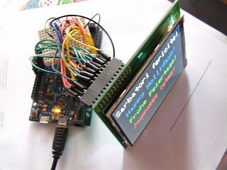
   I find a big display: 3.95" = 10cm: original use is for Raspbbery Pi board, but I put at Arduino Due development board because work like RPi with 3.3V logical level voltage... If I (or you) want to use with classical Arduino board (Uno, Mega, Nano, etc) must add two CD4060 chips (hex noninverting buffer)
 or buy another display with  logical interface and made as shield for Arduino board:
   After I talk with Vlad who use Arduino Nano and than Mega, I made next schematic:
    After I was documented, I use MCUFRIEND_kbv library with one example (single who works):
   I tested with good resuls using Arduino IDE 1.6.0, 1.6.6 and 1.8.0 software version on different PC with Windows XP or Windows 10.
   In test the display in Cristhmas period, so I put adequate texts:
  I made some movies, but I recommand you just:


Tuesday, December 20, 2016

Christmas tree with Arduino (2)

   In previous article I made a simple Arduino Chriostmas tree on breadboard with 9 leds, now I use a big piece of cardboard and cutter... I use 21 recovered leds (old leds) on 17 channels (I put 2 red leds in series) as in this schematic
   I use Arduino Nono board with ATmega168 because sketch is small (see christmas_tree_17channels.ino), but hase interesting effects (random leds lite, random delay between commands, random leds off), as in Carton Christmas tree with leds movie:
   After the Christmas tree was adorned I made new movies:

Tuesday, December 13, 2016

Christmas tree with Arduino


   Inspirred by Doz' Blog and article An Arduino Project: How To Make Flashy Christmas Lights Ornaments I made a Chistmas tree with 9 + 1 leds (9 in tree and one in Arduino nano board).
   Test schematic is
and real test assembly is
   I write 2 sketches, first (christmas_lights_1.ino) chose random the led for power on, wait 50ms, chose random the led for power off, second sketch (christmas_lights_1a.ino) is like first, just change time wirtting as be random from 10 to 100ms.
   I made 3 movie:
- with first sketch and all red leds - Arduino Christmas lights
- second sketch with all red leds - Arduino Christmas lights (2)
- second sketch with various leds - luminite pentru bradul de Craciun (3)

Friday, December 9, 2016

WeMos D1 board (with ESP8266) as Web Switch Control with autoreconnect to wi-fi network

    I tested an (retired now) WeMos D1 development board made with ESP8266EX microcontroller. About this board I found some info at https://www.wemos.cc/product
   For easy use as other Arduino boards, is ok to see this picture:
    Last project with this board is a Web Switch Control.
    For upload a sketch like in any Arduino board must use newish Arduino IDE software from https://www.arduino.cc/en/Main/Software to have this situation:
   For this, must go to FILES -> PREFERENCES
(see detailed data in article Placa NodeMcu v.0.9 programata in Arduino IDE).
    After that in TOOLS -> BOARD->BOARDS MANAGER you will see

and than
   Now, Arduino IDE software is ready for verify/compile and upload the sketch.
   First, I tested a sketch found at ESP8266 Community Forum in post named GARAGE DOOR OPENER EXAMPLE V2 (SEE POST #2). This sketch is writted by JoseAngel
   This sketch made a webserver using AJAX style (static page and just some datas is changes).
   My sketch led_controlled_from_webpage.ino has some change line, but I use same password (1234), and my led is at GPIO5 (D15/SCL) and GND (I not put 220-470 ohms resistor limiter, but is more good to put). I use 8087 port, but you can change to 80.
   I made WeMos board control a led using protected webpage using Ajax movie when you can how it use and control the led:
   After I tested about one mounth, I see some problemes, when wi-fi router is disconnected and reconnect.. so, I study but I give a tip from a collaborator, Mircea Craciun, who indicate my another post from ESP8266 forum.

   Now, my sketch led_controlled_from_webpage_auto.ino made autocreconnect in wi-fi network if apear some problemes.
   I put an LED for wi-fi error at  GPIO12 (D12/MISO) and GND.
   At first start, after restart or if link between router and WeMos is broken, second led blink until link with wi-fi is ok. You can see in ESP8266 Switch control with autoreconnect to wi-fi network movie how WeMos D1 board is working.
   At http://www.esp8266.com/wiki/doku.php?id=arduino-docs I found how I can use EEPROM memory from ESP8266EX microcontroller for store the state of led (ON or OFF) and number of good clicks (just for see how work the system).
   Last sketch, led_controlled_from_webpage_auto_eeprom.ino, has this feature with stored data in EEPROM. You can see that in ESP8266 Switch control with autoreconnect to wi-fi network (2) movie


Bibliography:

Wednesday, November 30, 2016

Another adjusting clock with alarm, hygrometer & thermometer on 1.8" ST7735 display

   I use feature from article Another adjusting clock with alarm & thermometer using DS3231 on 1.8" ST7735 display and change reading internal temperature of DS3231 with DHT22 senzor (AM2302), but you can use a cheaper and not very precise DHT11 senzor.
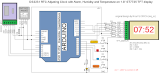
   Schematic is now:
   My test montage is
   By using educ8stv_rtctft160_alarm_dht.ino or much better educ8stv_rtctft160_alarm_eeprom_dht.ino sketch, on display you can see: name of day, date, hour clock, hour alarm, temperature and humidity
   In another adjusting clock with alarm, thermometer & hygrometer using DS3231 on 1.8" ST7735 display you can see info on display and hoe change/adjust hour, data, hour alarm, activate and deactivate alarm, etc:
   Alse, I made another movie, named another adjusting clock with alarm, thermometer & hygrometer using DS3231 on 1.8" ST7735 display (2), where I try to explain more detailed the feature of this clock...

Saturday, November 26, 2016

FDS-125 display with Arduino (2)

original article


   In previous article I present you how can conect an FDS-125 display to Arduino and how mase a simple, but "static" clock style
   For made an "dynamic" clock, I use some schematic
  I write in exitting sketch to display name of day in week in 2 language (romanian who is my navitve language and in english). It easy to change in your navive language by writting name of days in one line:
  Is very important to have in same subdyrectory of sketch font75.h file like in this picture:
  So, by uploading FDS125_clock1b.ino sketch, you cand see on display new info, beside date:
   In Arduino clock on FDS-125 display (2) movie you can see on FDS-125 display all info:
   After that, I put an AM2302 (DHT22) sensor for humidity and temperature, like in next picture:
   Newest skertch is FDS125_clock_RTC1c.ino and on display you can see new situations:
   Because, DHT sensor is too slow when is reading, I made some changes to see temperature and humidity in same times, also I chege font75.h file to display degree symbol instead ': 
  New sketch is FDS125_clock_RTC1c1.ino and this new style can be see it on Arduino clock on FDS-125 display (4)