Wednesday, May 20, 2015

Arduino thermostat with 2 thresholds on 4 digit 7-segment display

   This thermostat with few components has same schematic with previous thermostat:
 
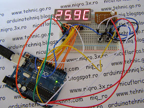
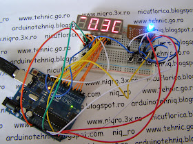
   Few pics with Arduino Mega board (must just few changes in sketch for works with Uno or Mega):
- desired temperature is ok:
- actual temperature is less than desired temperature:
- actual temperature is much than desired temperature:
   After push the MENU button, low threshold can be set:
and if I push the "-" button value is decrease with 1 degree Celsius at every push and if I push the "+" button value is increase with 1 degree Celsius at every push.
   If I push MENU button, high threshold can be set:
and if I push the "-" button value is decrease with 1 degree Celsius at every push and if I push the "+" button value is increase with 1 degree Celsius at every push. If high threshold is set less low threshold, Arduino automatically change high threshold = low threshold + 1 degree Celsius.
   Sketch for this thermostat is put at https://github.com/tehniq3/!
   For best results, I use internal reference (1.1V) and for Arduino Uno board in sketch must see:
and for Mega board must comment fisrt line and uncomment next line !!!
   Fist time when upload the sketch, must write default value for low and high thesholds:
after that must put comments and upload the sketch again:
   I made a movie with this thermostat, named Arduino thermostat with 2 thresholds

Arduino thermostat on 7-segment LED display

   I designed a thermostat with few components using an Arduino board.
   I use LM35DZ for temperture sensor, KW4-563ASA display (4 digit 7-segment with common anode), RGB led, 3 button (push button) for select and change the value for desired temperature and for hysteresis.
   I designed this schematic:
who is used also for an thermostat with 2 thesholds (must change the sketch).
   If measured temperature is less than desired temperture, blue led is on:
and if is to much, red led is on:
   If I push the MENU buton, display is change in:
(in right side, is "c" instead "C"). 
   If I push "-" button, temperature value decrease with 0.1 degree Celsius for each push, if I push "+" button, temperature increase with 0,1 degree Celsius for each push.
   After that, if I push again MENU button, I will see:
and I can change the value with 0.1 degree, like at desired temperature.
   Values for desired temperature and hysteresis are write and stored in internal EEPROM memory of microcontroler (any Arduno board has an microcontroller on it.)
   For easy understund this, I made a movie named Arduino thermostat
   Skech for this thermostat is put on https://github.com/tehniq3/thermostat !!!

PS:  Fist time when upload the sketch, must write default value for desired temprature and hysteresis:
after that, must comment the 3 lines:
   Actual sketch work with Arduino Uno board and you can see:
but for work with Arduino Mega board you must comment first line and uncomment second line:
PS2: If you want to connect a relay for control a heater system, subroutine leduri() must be changed in:
void leduri() {
 digitalWrite(CALD, LOW);
 digitalWrite(RECE, LOW);

if ( t0*10 < tset ) 
{  digitalWrite(RECE, HIGH);
   digitalWrite(CALD, LOW);
   pornire = 1;
}
if ( t0*10 > tset + dt ) 
{  digitalWrite(CALD, HIGH);
   digitalWrite(RECE, LOW);
   pornire = 0;
}

if (( t0*10 <= tset+dt ) && ( t0*10 >= tset )) {
if (pornire == 1)
{  digitalWrite(CALD, LOW);
   digitalWrite(RECE, HIGH);
}
if (pornire == 0)
{  digitalWrite(CALD, LOW);
   digitalWrite(RECE, LOW);
}
}
}
and at begin of sketch must define int pornire; and in setup must put pornire = 0; !!
   You can download changed sketch from https://github.com/tehniq3.
   In movie namend Arduino thermostat (2) you can see the changed style, like usual thermostat for a heater:

Friday, May 8, 2015

Revive the dead fake FT232R

   If you buy a USB FTDI interface with FT232R from China, like this
and use a older Windows (XP) is ok, but if you use Windows 7 or newer Windows operating system, you will see on screen 
   In DEVICE MANAGER you will see
  If you have a original chip, all are ok and in DEVICE MANAGER you can see:
   For use the module with fake FT232R you can use original software named FT Prog (read User manual too). Must change the PID from 0000 in 6001 (like at original chipset):
   If this method not work you can use a modified 2 inf files in original driver directory 

or add 2 modified inf files like me:
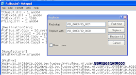
   In ftdibus.inf and ftdiport.inf (or ftdibus2.inf and ftdiport2.inf) must replace VID_0403&PID_6001 with VID_0403&PID_0000.
   You can download the modified files from https://github.com/tehniq3/FT232R_PID000...
   After that, you must update driver for FT232R with changed files and you will see: